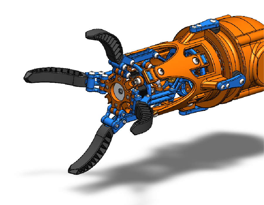
Designing a robotic arm featuring a claw mechanism and analyzing the power and torque requirements at each joint to support a maximum load of 10 kg.
Approach
These are the steps I will take to achieve our objective for this product:
Designing a robotic arm for automation
Using Block and Kinematics
Complex Assembly
Motion study for required torque and Power
Product and exploded view Animation
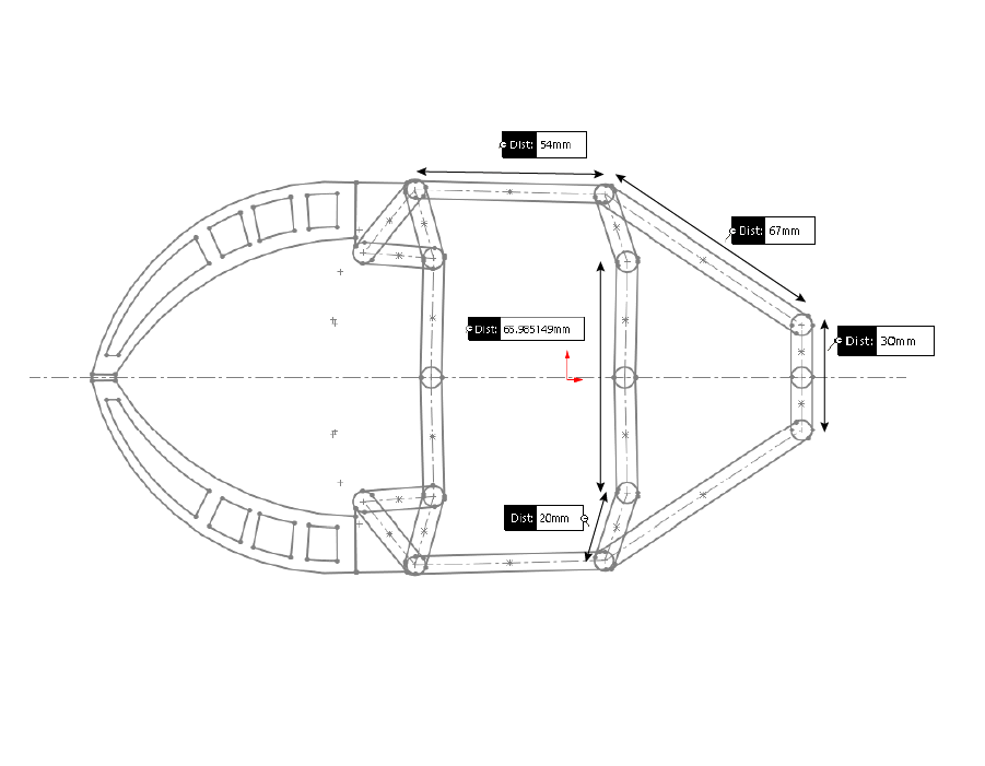
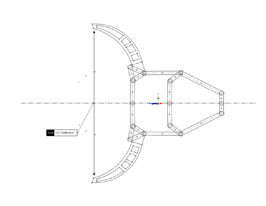
Blocks and Kinematics
I used blocks to determine the overall dimensions of the claw design and assess whether the kinematics function as expected. In SolidWorks, blocks are an excellent tool for designing and analyzing the kinematics of a product, helping to identify potential issues early and minimizing design changes during the modeling phase.
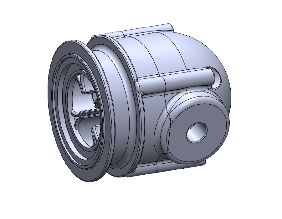
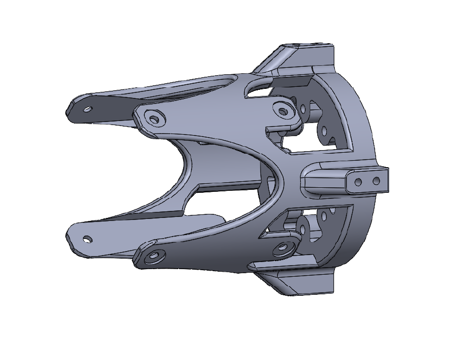
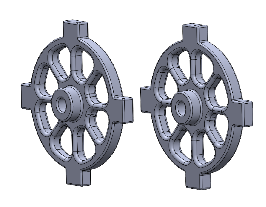
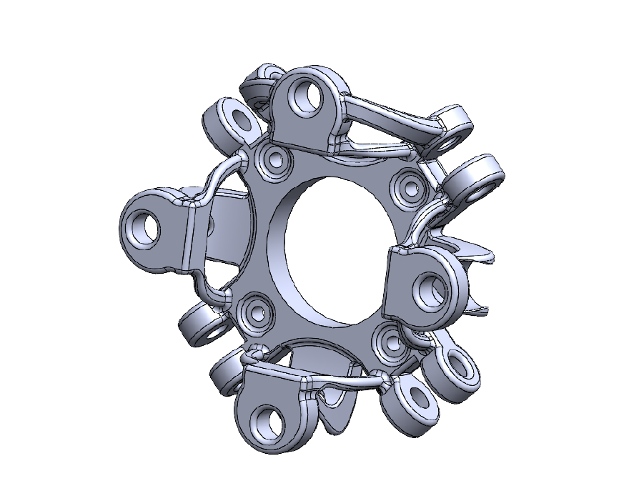
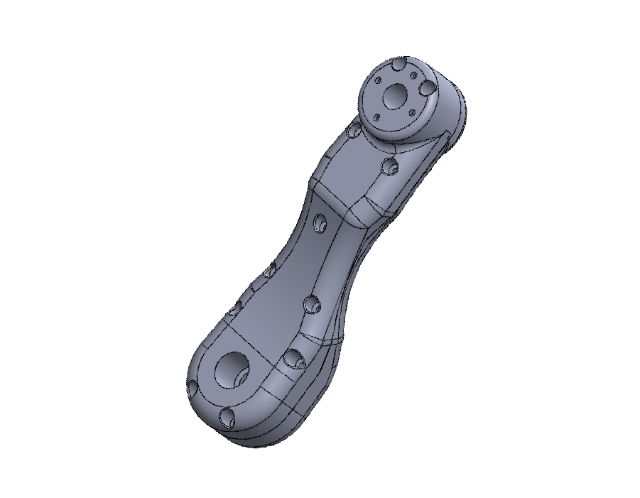
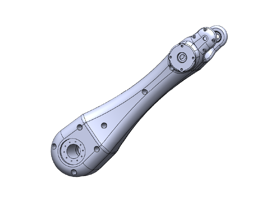
Modeling parts
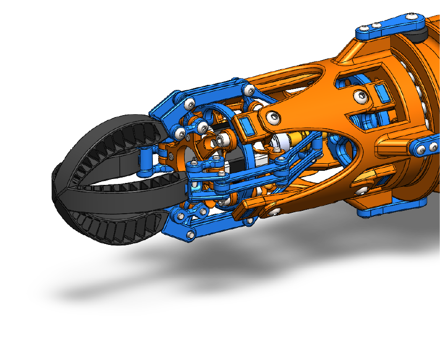
Since this is an industrial product, most of the parts are designed using solid body modeling techniques to ensure strength and durability. The product will be assembled using screws, so it’s essential to create precise slots that will connect the various parts securely.
Extruding and cut-extruding are the primary techniques used to create most of the parts, allowing for the necessary shapes and features. The arms, in particular, are designed to be hollow, with internal supports for added structural integrity while reducing material weight.
To streamline the design process, all screws and bearings will be sourced from the SolidWorks library. This approach eliminates the need for manual modeling of each component, saving time and ensuring the parts meet standard specifications for fit and function.
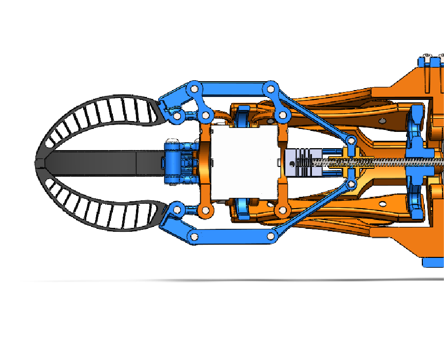
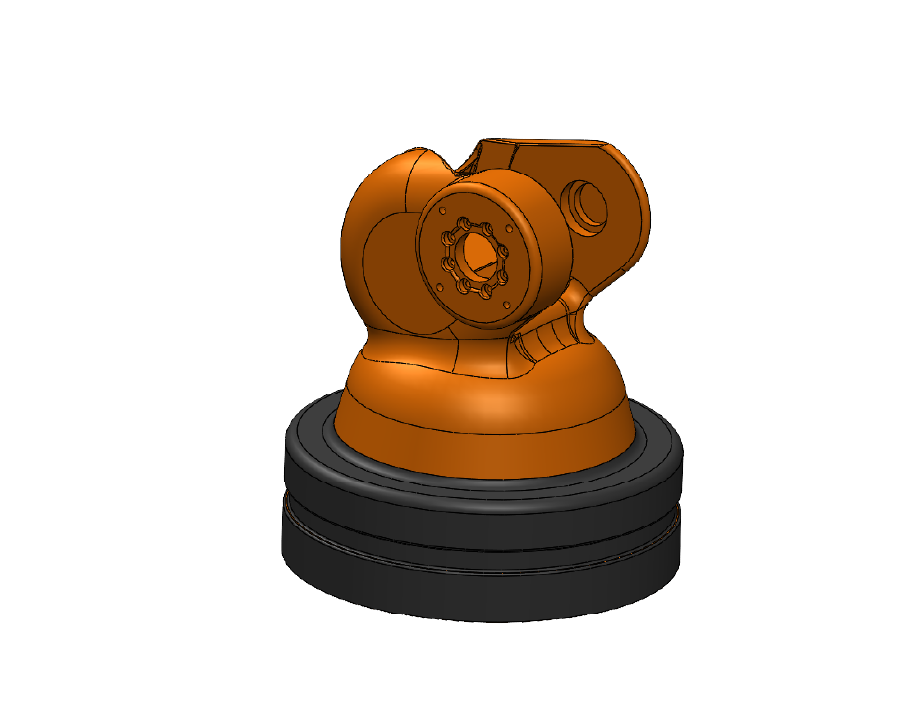
Complex Assembly
The assembly of this product is relatively complex due to the large number of parts and the need to ensure that the entire assembly has the necessary freedom of movement to function effectively. It’s crucial to maintain proper alignment and clearances to achieve optimal performance across all moving components.
To simplify the process, I’ve made an effort to use standard mates as much as possible. This is particularly important since we’ll be conducting motion analysis later in the design process. Motion analysis in SolidWorks doesn’t fully support some of the more advanced mates, so using standard mates ensures compatibility and allows for more accurate simulation and performance testing.
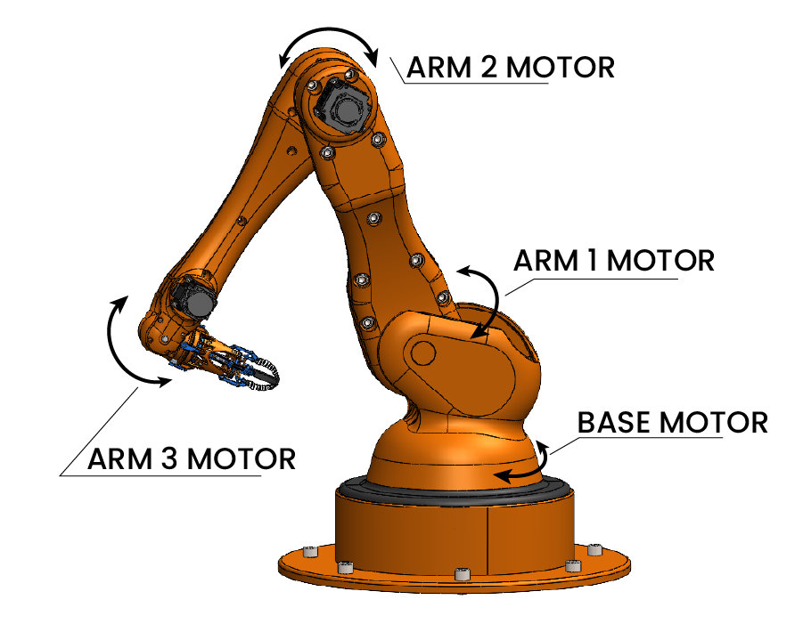
Motion Analysis setup
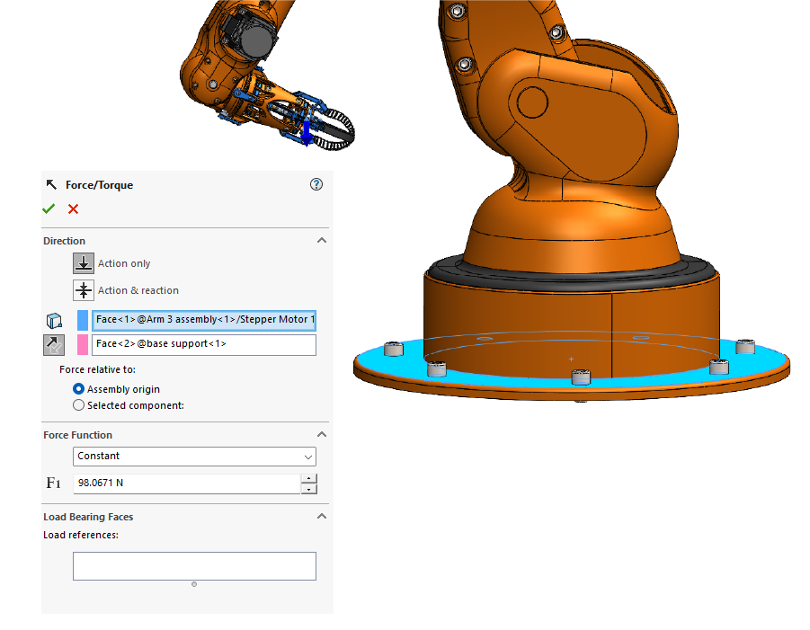
For the motion analysis, I added motors to each joint that is intended to move, enabling precise control of the arm’s movements. I also enabled gravity in the simulation and applied a 10 kg load to the claw to accurately replicate real-world conditions and test the arm’s performance under typical operational stress.
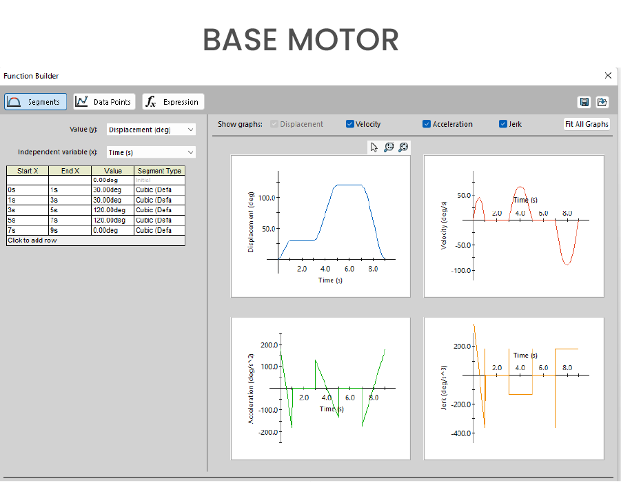
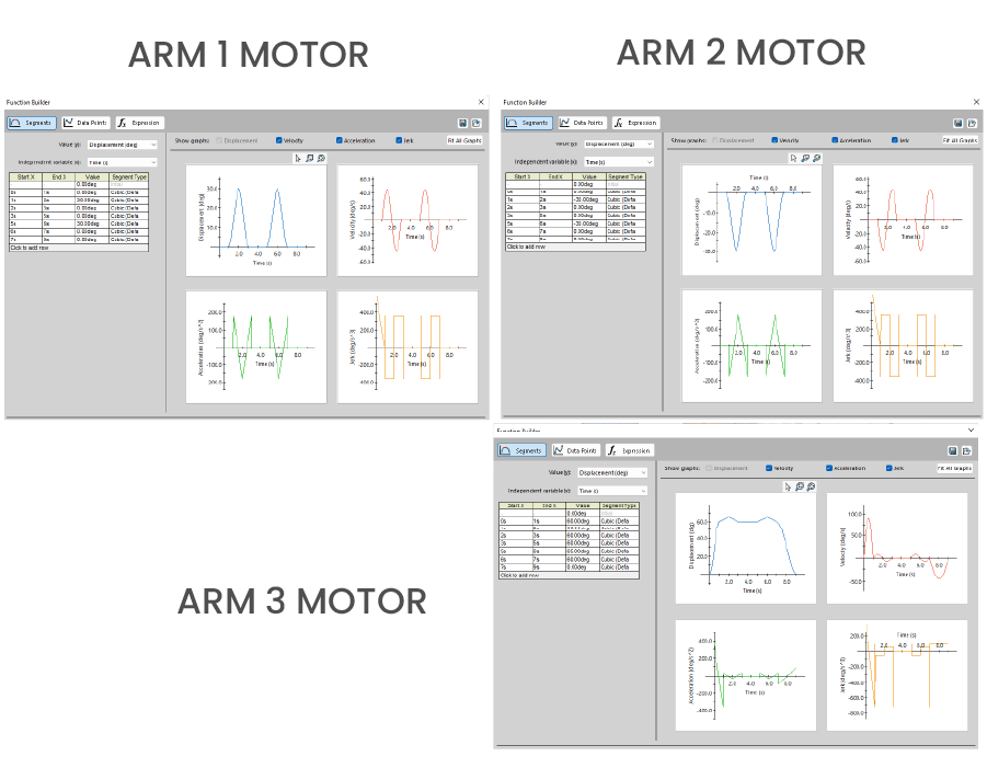
To control the motors, I used segments to define the desired angles for each joint and the time it should take to move between them. This allows for smooth, controlled motion throughout the entire process.
The motion analysis simulates the arm performing a task where it picks up an object and places it in a different location. This gives a clear representation of how the arm will function in real-world scenarios and helps to ensure that the design will operate effectively under the expected loads and motions.
Results Extraction
Here are the results from our motion analysis and how they guide design decisions:
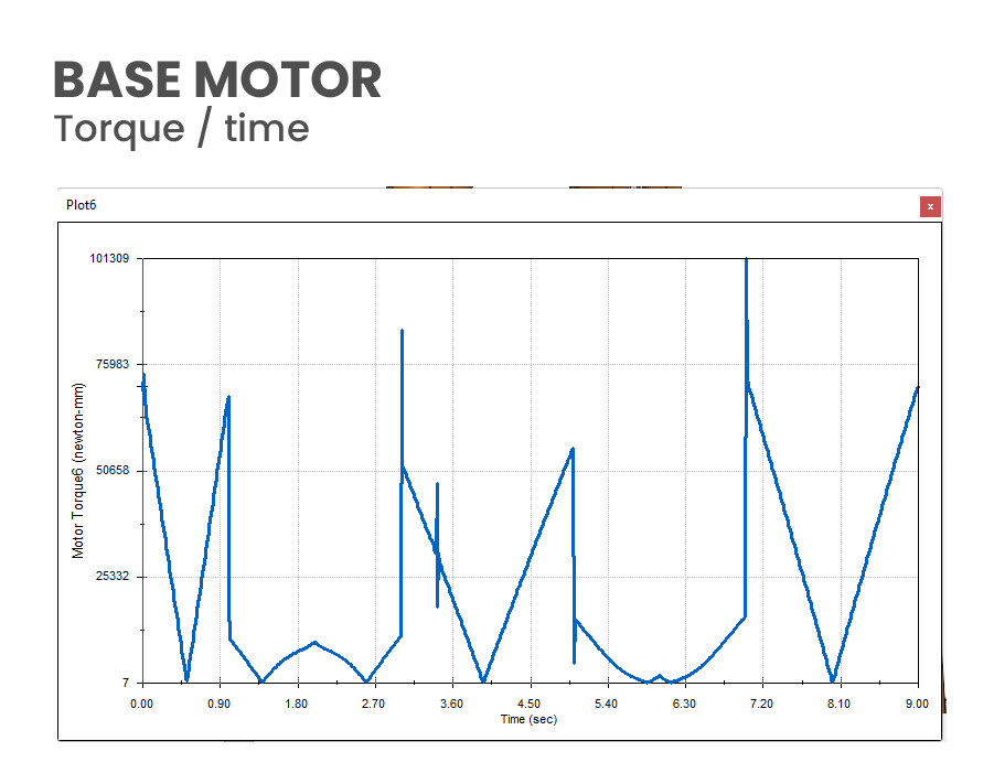
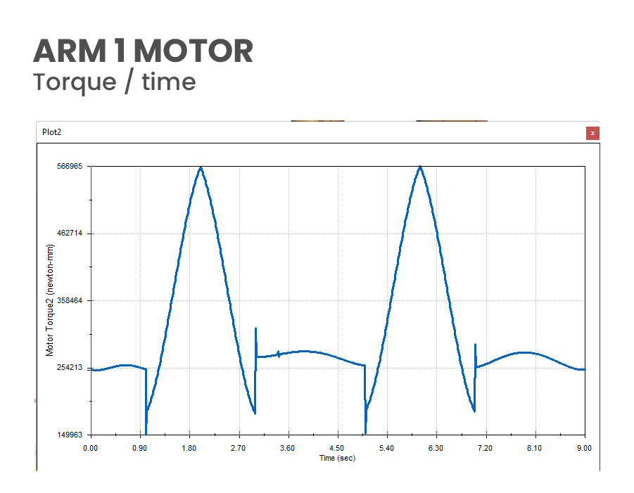
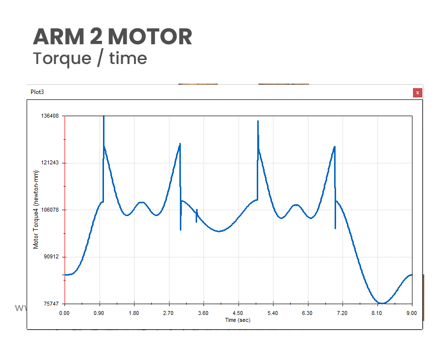
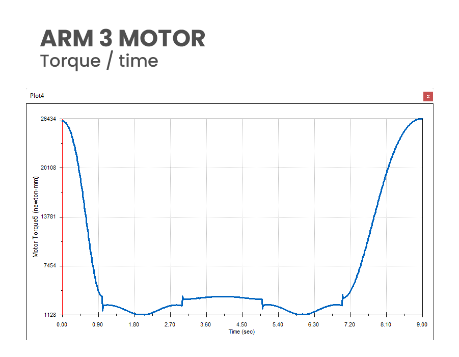
Torque vs. Time Plots: These plots show the maximum torque each motor requires, helping us design the right gear configuration and determine the arm’s maximum speed. The data also helps smooth the motion, reducing jerks that could affect the product’s structural integrity.
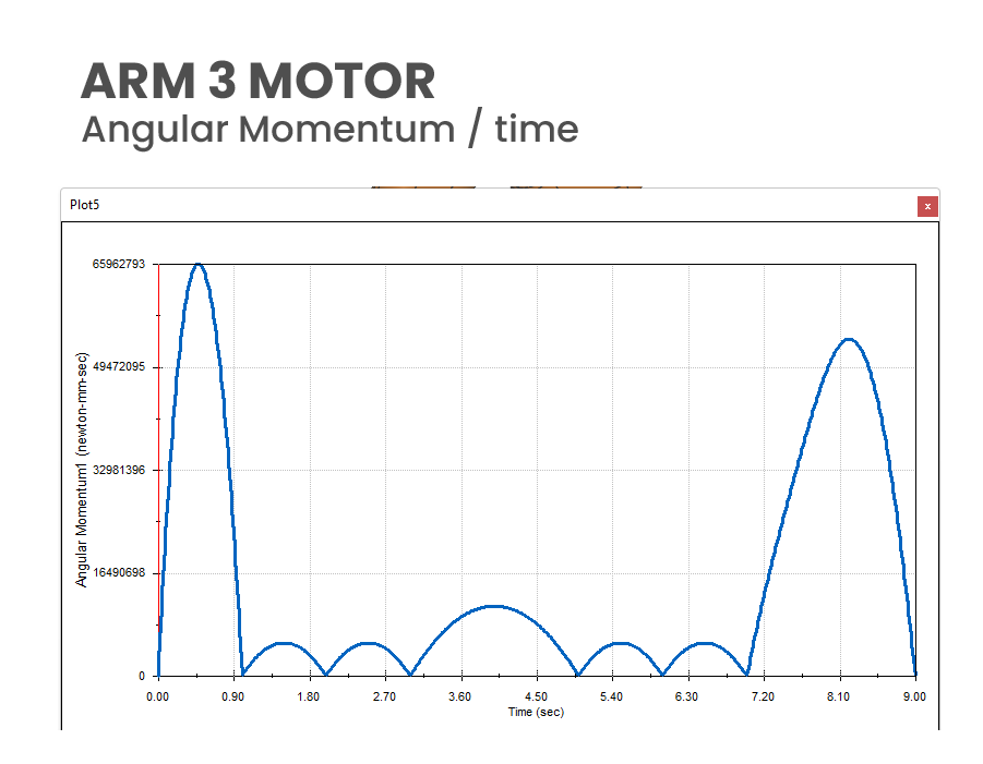
Momentum vs. Time: This data reveals the acceleration and momentum of each part, aiding in power requirement decisions and ensuring efficient motor selection while minimizing energy use and wear.
Possibilities
Motion study provides a variety of possibilities for simulating and analyzing the movement of mechanical assemblies. Here are some key capabilities and possibilities you can explore with motion study:
Simulation and visualization of assembly motion to check interactions and alignments.
Performing kinematic analysis to study movement based on mates and constraints.
Conducting dynamic analysis with forces, torques, and gravity for real-world testing.
Calculating torque, force, and speed for motor sizing and gear selection.
Using collision detection to ensure parts do not interfere during movement.
Simulating real-world conditions like gravity, friction, and applied loads.
Creating animations to demonstrate design functionality for presentations.
Evaluating performance for efficiency, energy consumption, and stability.
Conducting advanced motion analysis to simulate forces and calculate stresses.
Have a project in mind!
Let's work Together
If you have a vision or concept you'd like to bring to life, let's collaborate to make it happen. With a focus on creativity, innovation, and precision, I offer tailored solutions to meet your unique needs.