
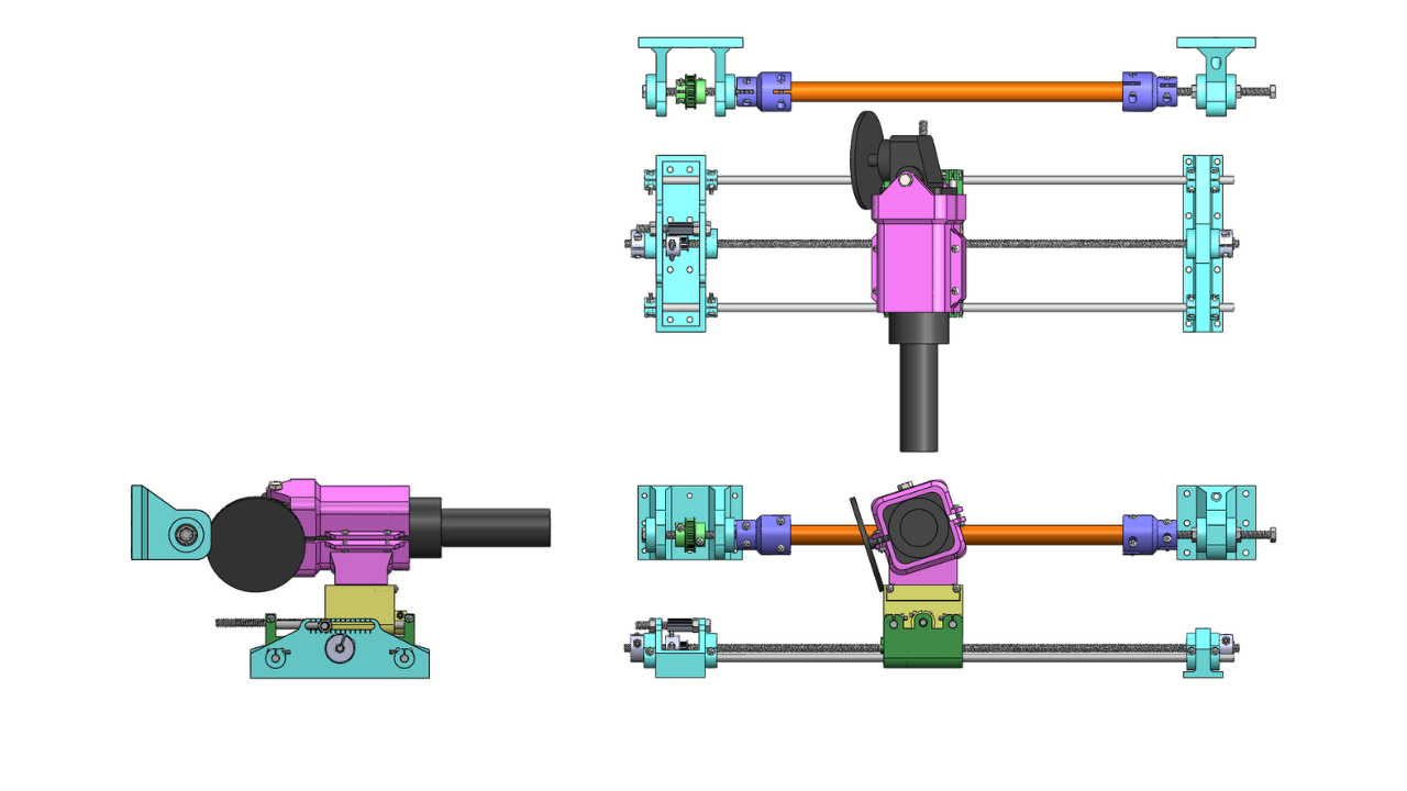
Extrsion Screw from scratch using 3d printed parts
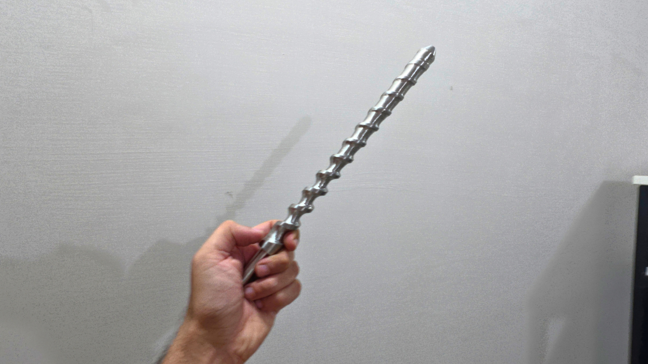
This projects involves grinding an extrusion screw for making you own 3d printing filament.
Overview
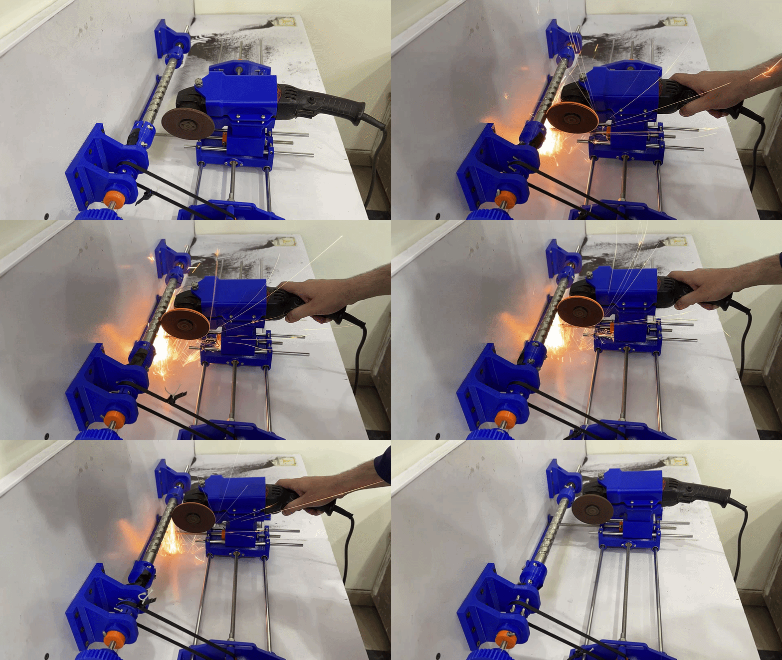
Designing and manufacturing an extrusion screw at home without access to industrial machining equipment is a challenge. For this project, I designed and used custom 3D-printed parts to grind my own plastic filament extrusion screw at home.
The goal was to develop a practical, low-cost solution that could help makers and DIY enthusiasts manufacture their own extrusion screws using commonly available tools and a 3D printer.
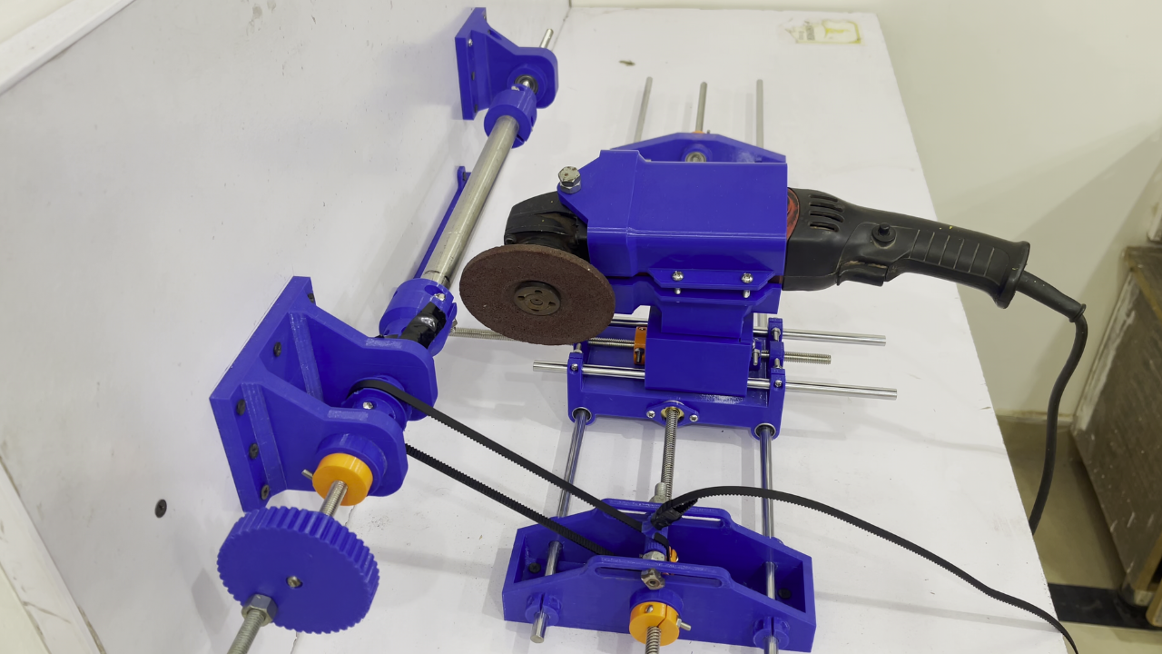
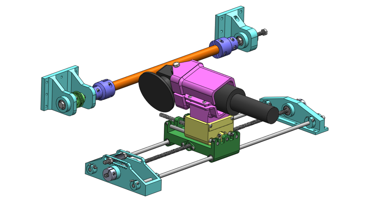
I designed the printed components to hold and guide the workpiece during the grinding process, making it easier to achieve the required screw geometry with basic workshop equipment. This project combines mechanical design, 3D printing, and hands-on manufacturing to demonstrate how custom-designed tools can make otherwise difficult processes more accessible.
What’s Included?
- 3D models of the custom-designed printed parts.
- Files to help you reproduce the setup for your own project.
- A practical example of using 3D printing to simplify a metalworking process.
Build It Yourself
I’m sharing the project files on my website so other makers, engineers, and 3D-printing enthusiasts can experiment with the design, reproduce the setup, and adapt it to their own requirements.
Whether you’re building a plastic filament extruder or simply exploring DIY manufacturing techniques, I hope this project helps you turn your ideas into reality.
Download the files, build your own setup, and share your results!
What needs to be updated?
I made this setup for a 20mm dia screw with 20mm pitch. If you want to make some other screw you need to update these parts:
1. “m8 to m20 connector” These helps to connect the 8mm bolts to the workpiece which is 20mm in my case. If you want to make a 16mm dia screw you need to update it.
2. “Grinder Attachment”, I designed this attachment to work with almost every 4″ angle grinder. This is why it has multiple screws and a sleeve to adjust for different size grinders. If it still doesn’t work you will need to adjust it or contact me, I will do that for you.
3. “Timing pulleys”, I use 20 to 50 teeth timing pulleys which gives me 20mm pitch for the screw. If you want to make a 16mm screw (for example) OR want to change the pitch one of these pulleys will need to be adjusted.
Note: This is a DIY workshop solution, not an industrial machining fixture. Use appropriate guarding, secure clamping, and eye protection when grinding metal. Inspect all 3D-printed components for wear or damage, and keep them away from direct contact with the grinding wheel and excessive heat.
Parts List:
You will need these extra parts other than 3d printed ones. I have added Mcmaster part no for you to either order directly or get the dimensions of the parts to order from other platforms. These are also added in the BOM drawing.
License: free for personal and university use.
Please credit Bazal Junaid and link back to my website www.bazaljunaid.com
For commercial use, contact me first at
[email protected]
Download Files
Free to use. No sign-up needed.
CAD Files (STEP)
Learn, share, and get feedback with other makers.
Print Files (STL)
Learn, share, and get feedback with other makers.
Drawings/Instructions (PDF)
Learn, share, and get feedback with other makers.
Everything (ZIP)
Learn, share, and get feedback with other makers.
License: free for personal and university use. Please credit Bazal Junaid and link back to this page. For commercial use, contact me first.
Build it, then share it
Built this? Post it in the community and I’ll feature the best builds. Stuck? Ask for help there.