Designing a modern air purifier for desk that can be manufactured by Injection molding and can clean air at a minimum rate of 5 ft3/min.
Approach
These are the steps I will take to achieve our objective for this product:
Designing the product using AI
Design for Manufacturing (DFM) consideration
Surface modeling for consumer product
Performing CFD analysis to find the perfect fan RPM
Creating Product Renders and Animation
AI Product Design
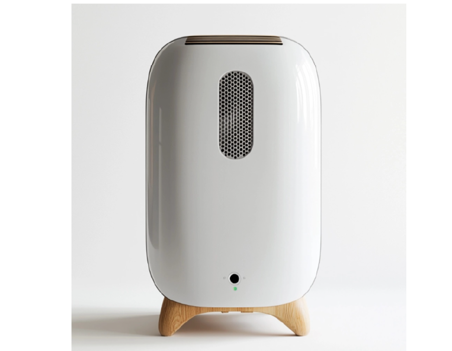
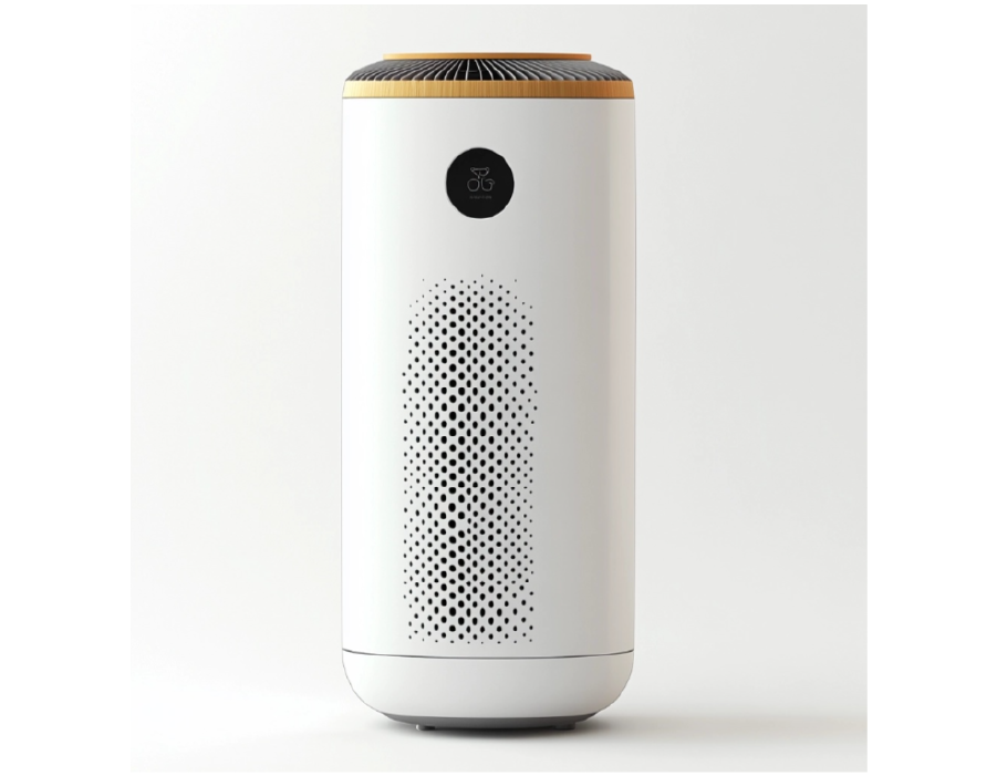
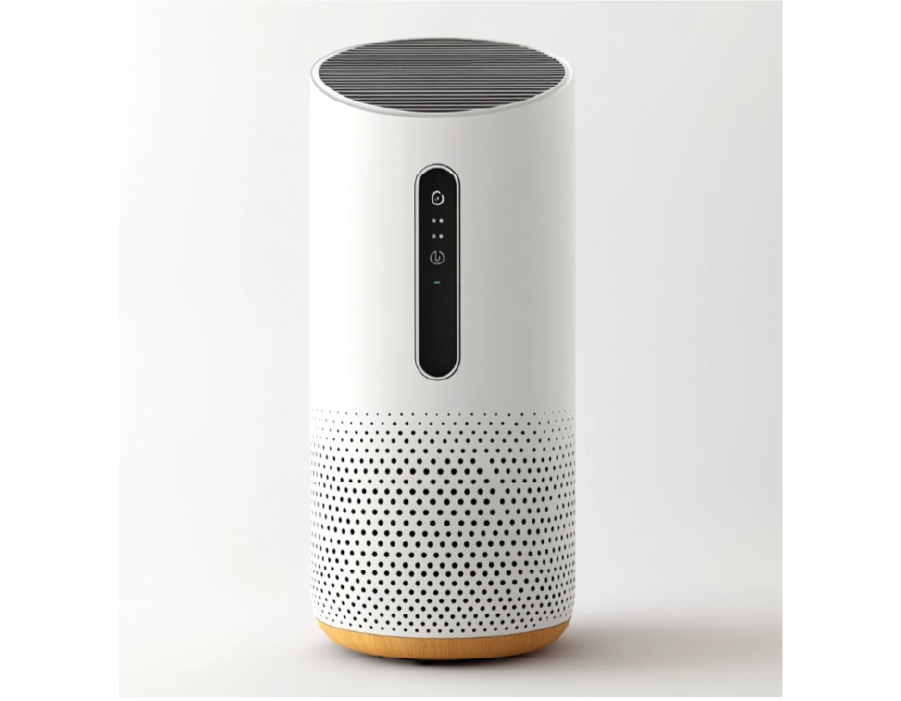
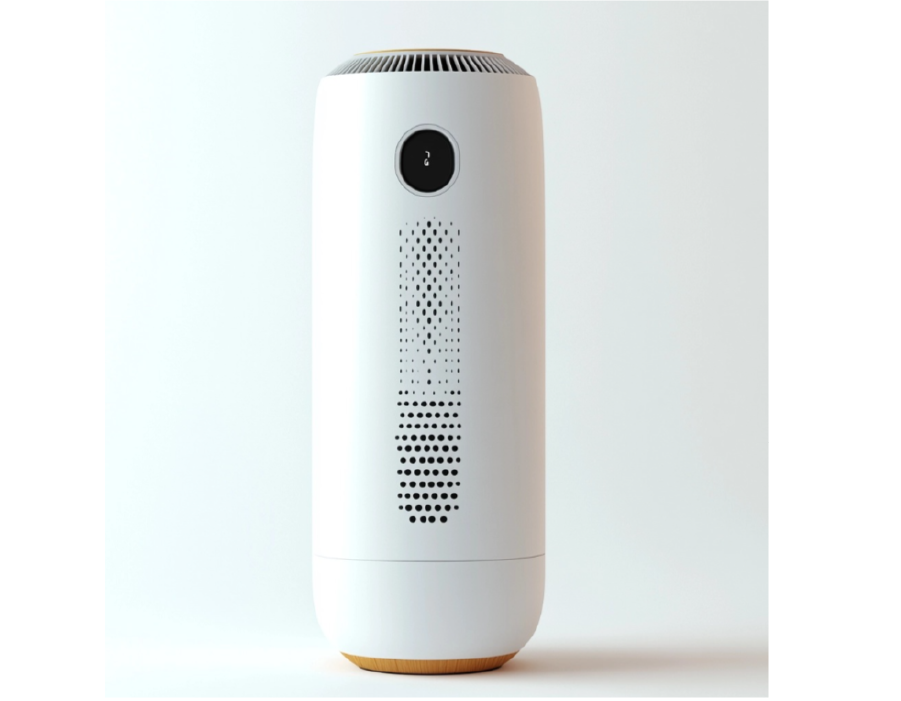
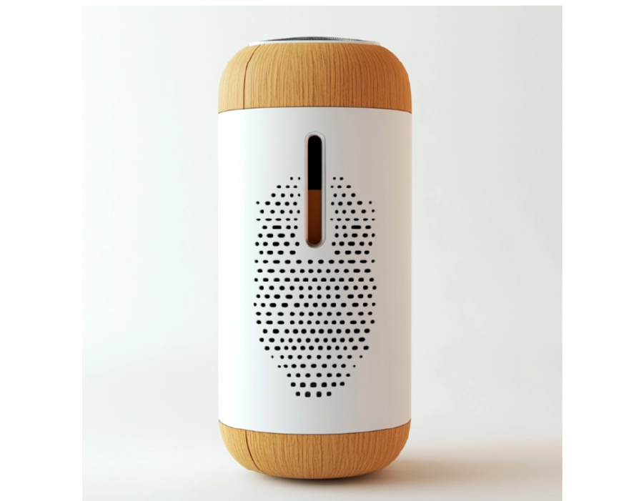
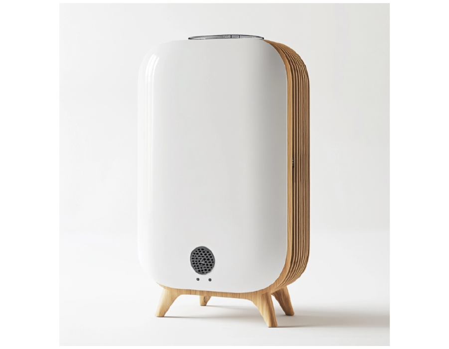
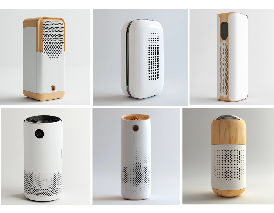
I will harness the power of AI to design the product, using a variety of AI tools like MidJourney, Vizcom, and Krea. This is the prompt I started with, which provided numerous options.
Prompt:product design of an air purifier, Funtional rectangluar taller, scandanavian interior design, have small hole on side and vents on top, white background, realistic 4k
From these, I selected two designs to combine. For any design, it’s crucial to ensure that it is both manufacturable and functional.
Modeling body parts
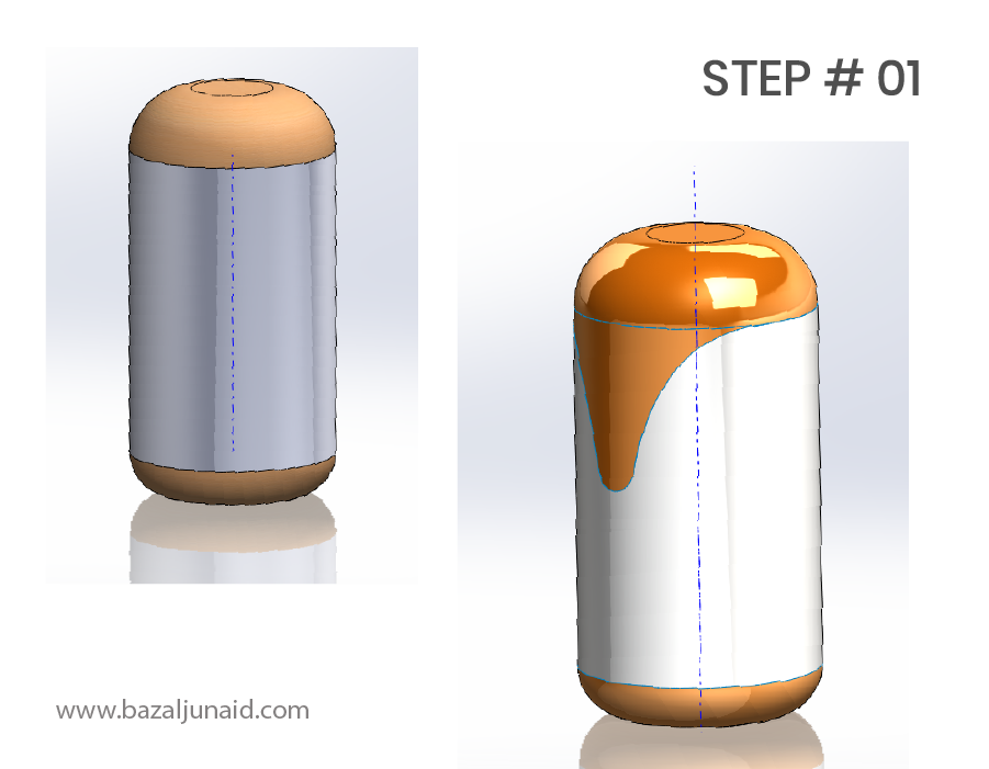
I began with surface modeling, creating the entire product within a single part file. I then used the ‘Save Bodies’ feature to separate the components.
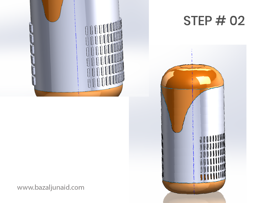
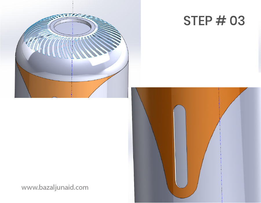
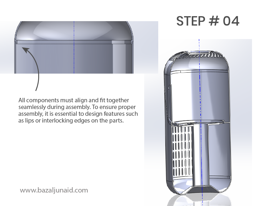
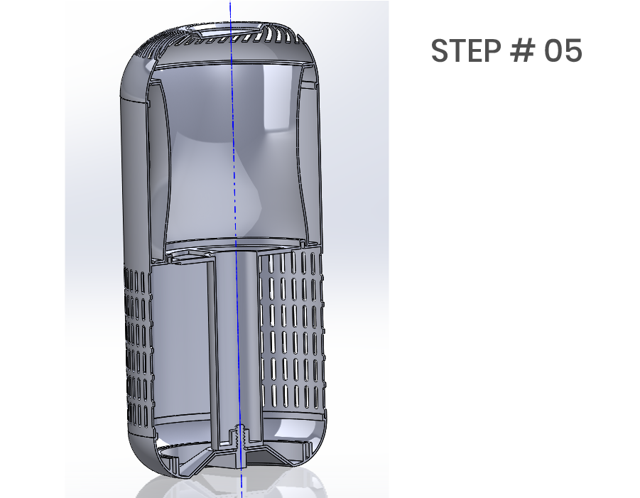
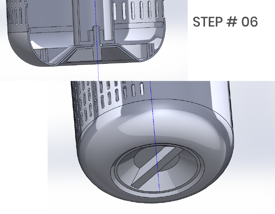
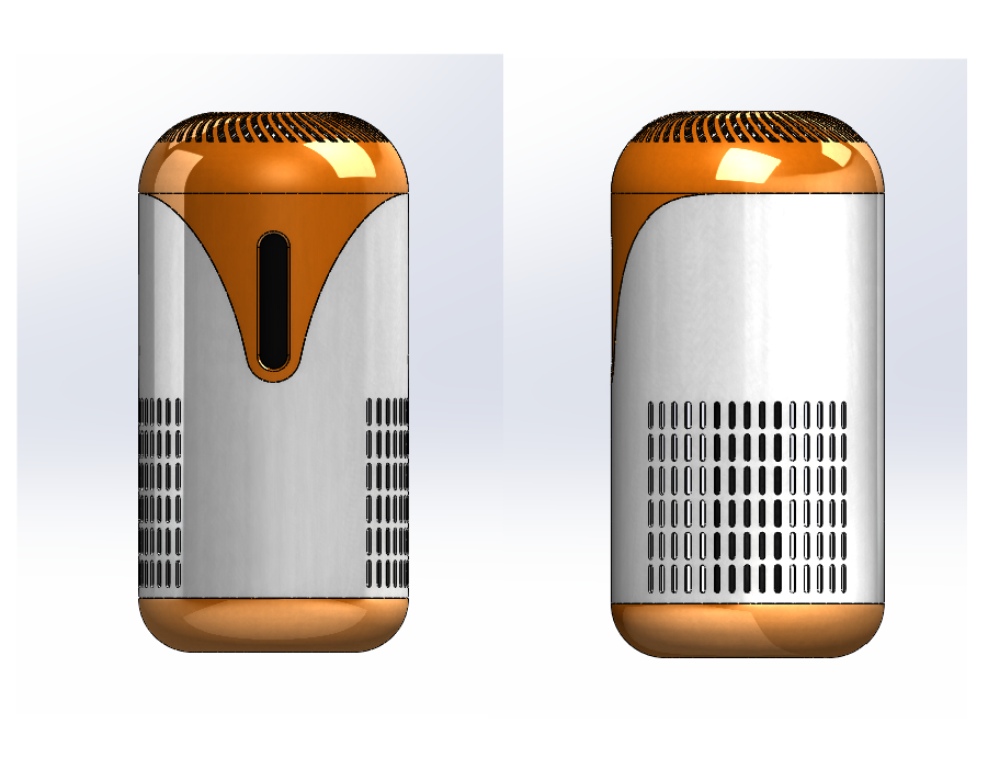
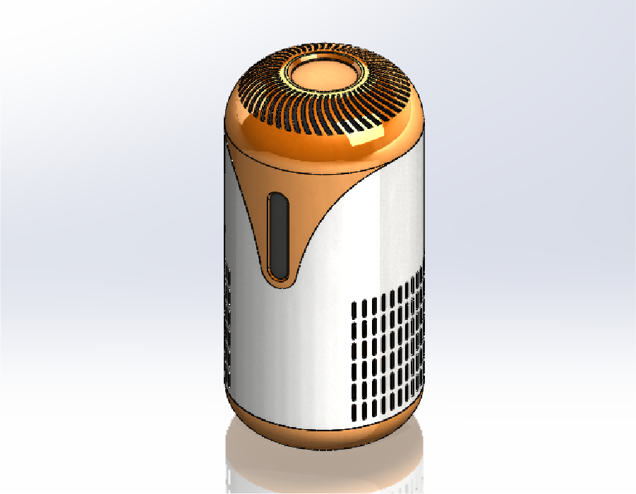
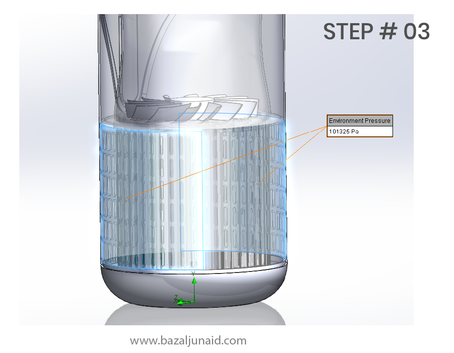
Step 1: Defined the overall shape and divided it into three sections to ensure manufacturability. Step 2: Added vents for air intake on both sides. Step 3: Incorporated vents for the outlet and created slots for control buttons. Step 4: Designed an internal structure to support all components securely. Step 5: Made the part hollow to allow for optimal airflow and to separate the electronics from the air. Step 6: Designed a screwed component for easy installation and consumer-friendly filter cleaning
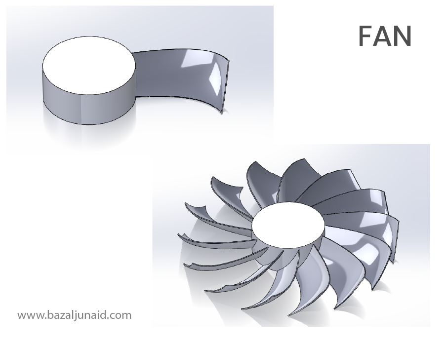
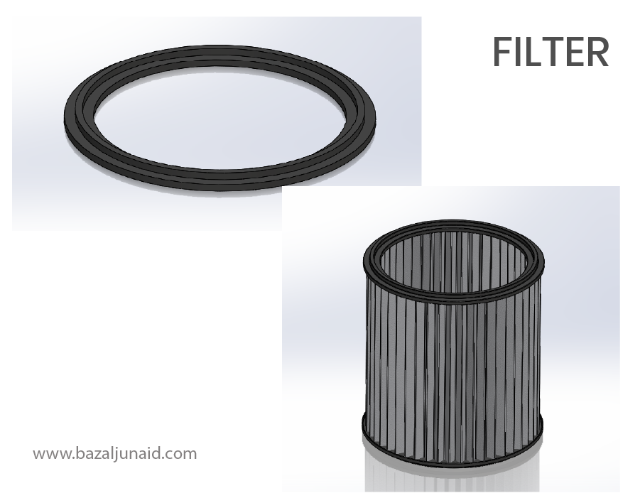
Modeling Fan and Filter
I modeled the fan and filter separately, keeping the design straightforward. We can also opt for standard fan and filter components from the market and outsource their sourcing.
CFD Study at 1200rpm
We will conduct a CFD simulation to determine the flow rate at the outlet at 1200 RPM.
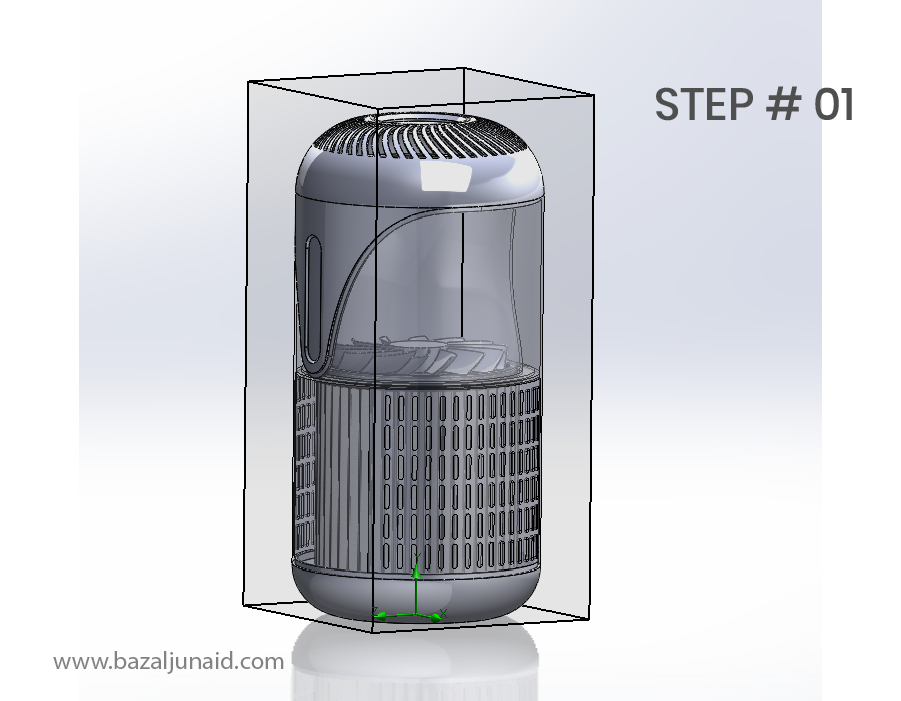
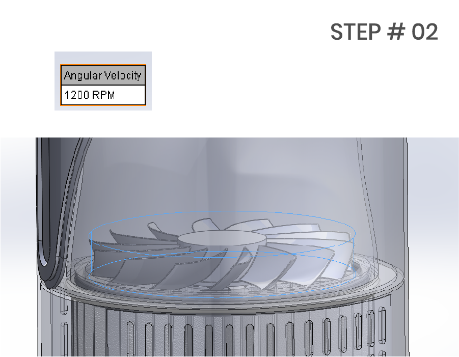
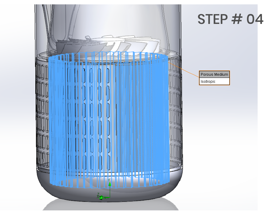
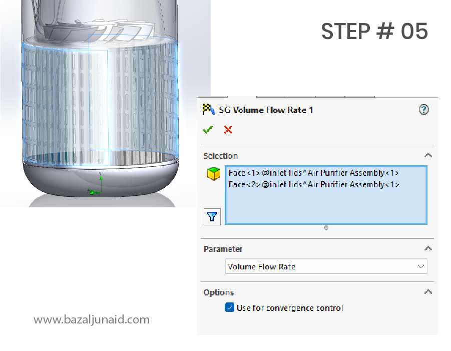
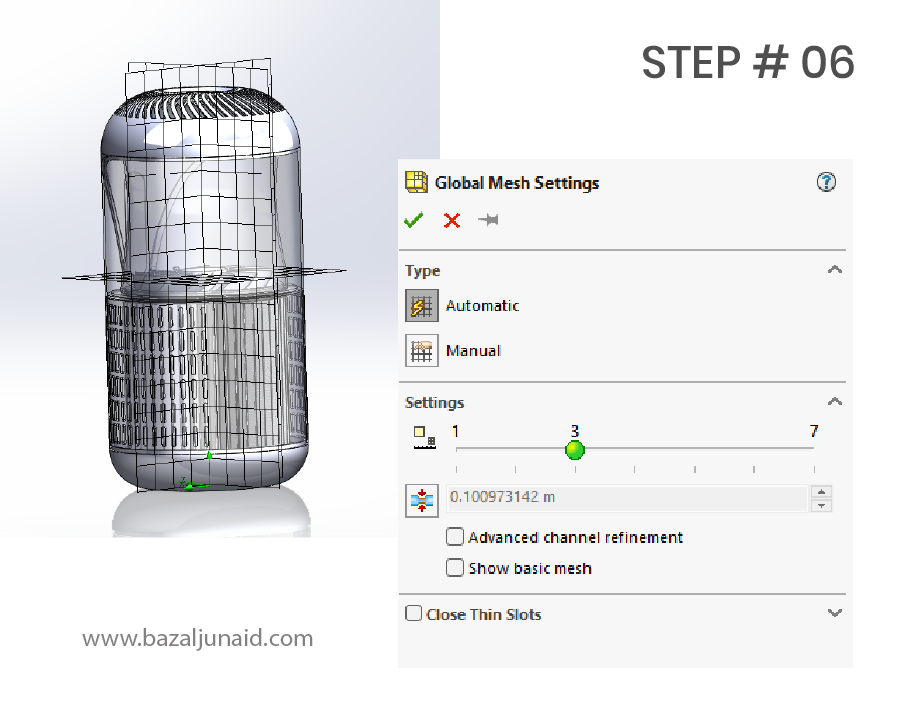
Step 1: I created lids for the inlet and set up the computational domain, using an internal study with air as the medium. Step 2: Defined the rotational region for the fan, setting the rotational speed to 1200 RPM. Step 3: Configured environmental conditions for the inlet. Step 4: Set up the filter as an isotropic porous material with 50% porosity. We can create a custom material for more detailed analysis if needed. Step 5: Established a surface goal at the inlet to calculate the total airflow rate cleaned per minute. Step 6: For this analysis, I used the default mesh quality, which is automatic and standard. We can refine the mesh later for more accuracy.
Results evaluation
Here are the results of our simulation and how we can make decisions based on these findings:
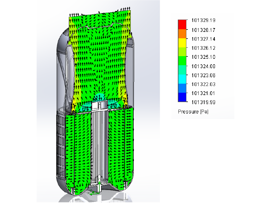
Pressure Cut Plot: There’s minimal pressure difference across the system, except at the edges of the fan. We can improve the funnel shape in this area to optimize pressure distribution.
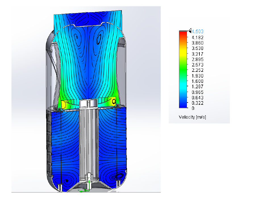
Velocity Cut Plot: While there are a few spots with recirculation, the issue is not severe or concerning at this stage.
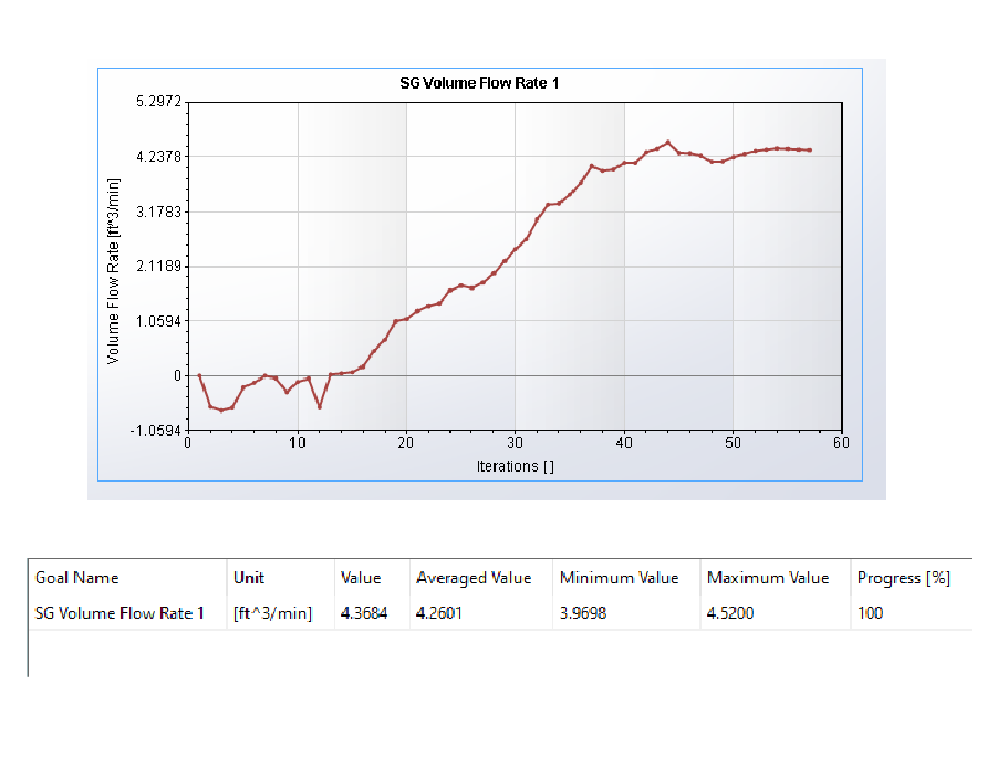
Surface Goal: We achieved a flow rate of approximately 4 CFM at 1200 RPM. Our target was 5 CFM, so we will conduct a parametric study to determine the exact fan RPM needed to meet this goal.
Flow Trajectories: The flow trajectory shows a swirl of air inside. While this could potentially be addressed by adding stators above the fan, the current swirl does not impact our goal or the overall structure of the product.
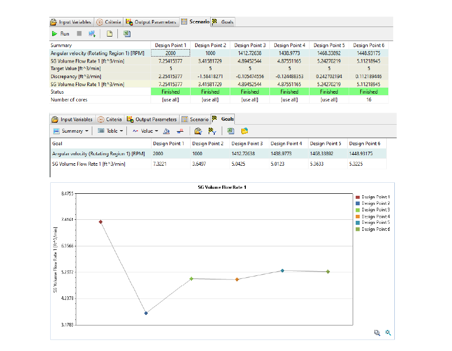
Parametric Study
The objective of this parametric study is to determine the fan rpm required to achieve a volume flow rate of 5 cfm. For the calculations, I selected the “Goal Optimization” method.
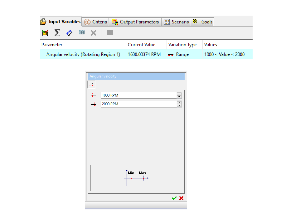
Input Variable: We defined a range of rpm values from 1000 to 2000, as prior analysis indicated that the required rpm is likely to fall within this range.
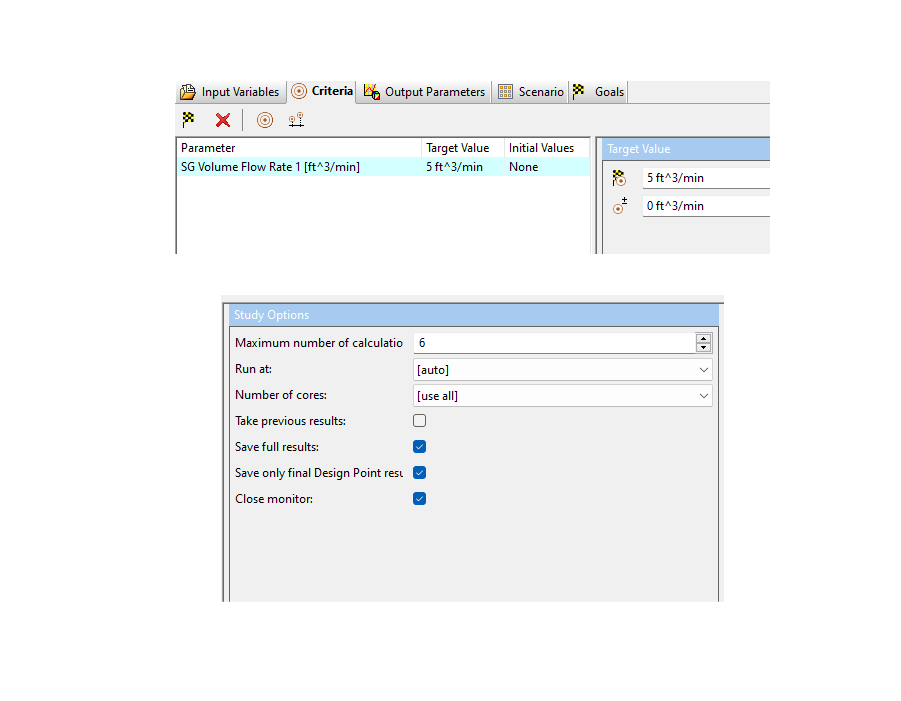
Target Value: The target volume flow rate is set to 5 cfm, with a maximum of 6 calculation iterations.
Results and Goal: At the completion of the 6th design iteration, the fan rpm was determined to be 1449 rpm, resulting in a flow rate of approximately 5.11 cfm, with a discrepancy of 0.112%. This result is considered acceptable for the product.
CFD Analysis Possibilities
CFD (Computational Fluid Dynamics) analysis offers numerous possibilities when designing an air purifier, as it helps simulate and optimize airflow, pressure distribution, filtration efficiency, and system performance. Below are key possibilities where CFD can play a vital role in the design process:
1. Airflow Distribution and Path Optimization
2. Pressure Drop Analysis
3. Fan Design and Motor Sizing
4. Filter Efficiency and Flow Resistance
5. Sound and Noise Optimization
6. Contaminant Transport and Particle Filtration (Particle study)