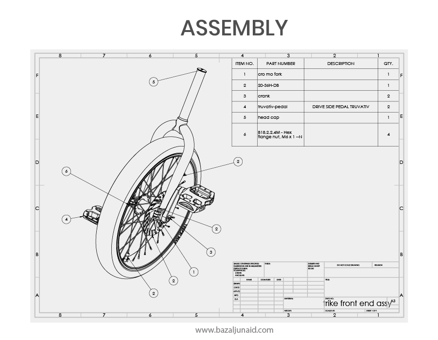
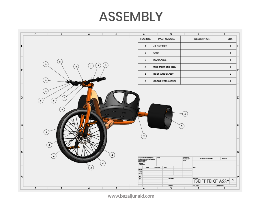
Designing a drift trike frame, seat, and wheels while analyzing the stresses, deformations, and Factor of Safety to support a maximum load of 200 kg.
Designing a drift trike frame, seat, and wheels while analyzing the stresses, deformations, and Factor of Safety to support a maximum load of 200 kg.
For a systematic and efficient process, these steps were followed to ensure our objective:
This is a sketch-based modeling project, meaning we don’t have a finalized product design yet, only the initial specifications to guide us. As we proceed, we’ll add feature supports for strength and incorporate any necessary details throughout the design process. The sketch will serve as a reference while designing each part of the product. The three primary custom parts to be designed are the frame, saddle, and rear wheels, while the remaining components (such as the front wheel, pedals, and handlebars) can be sourced externally.
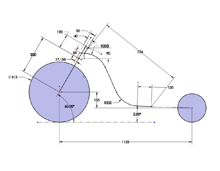
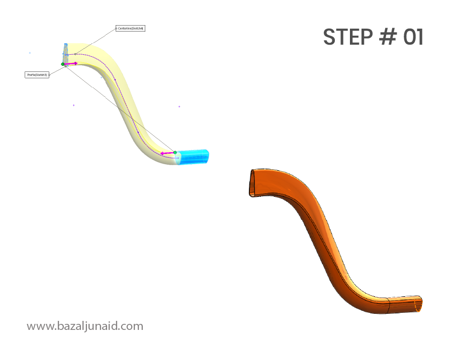
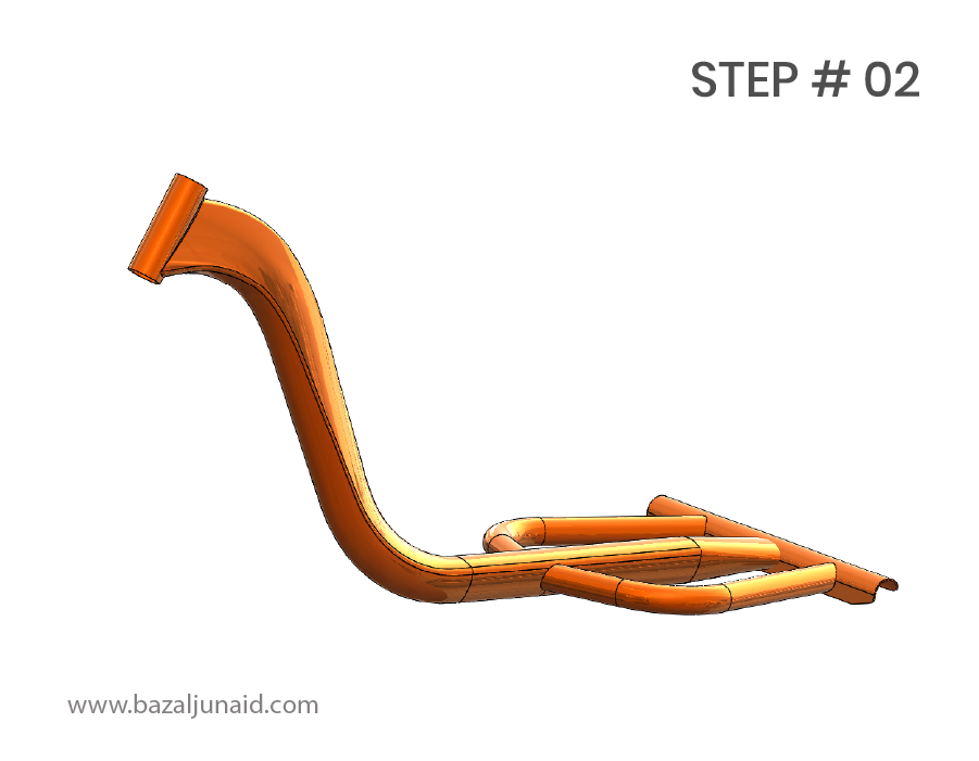
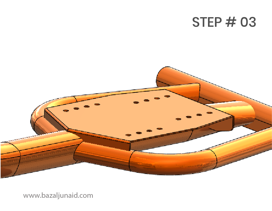
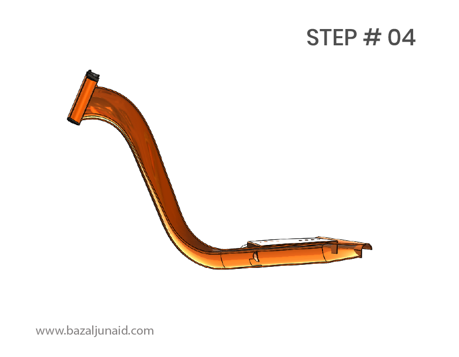
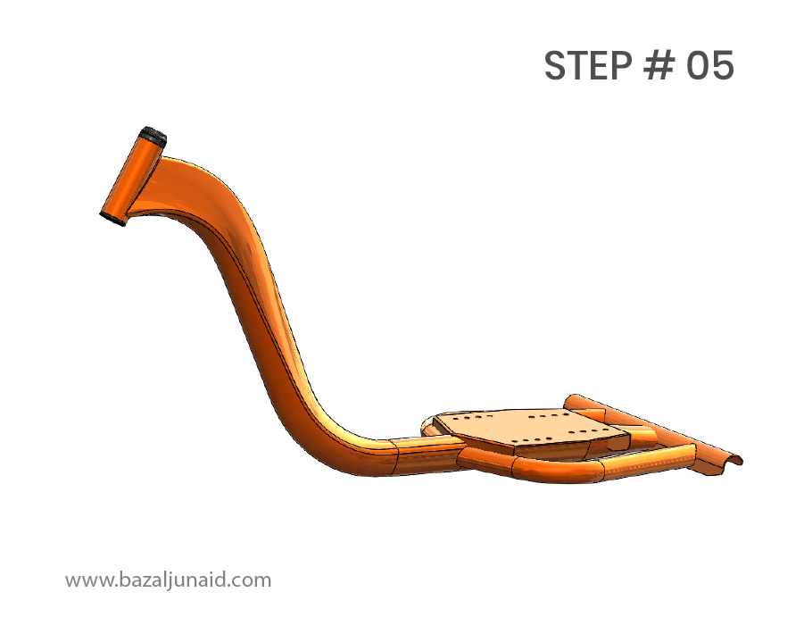
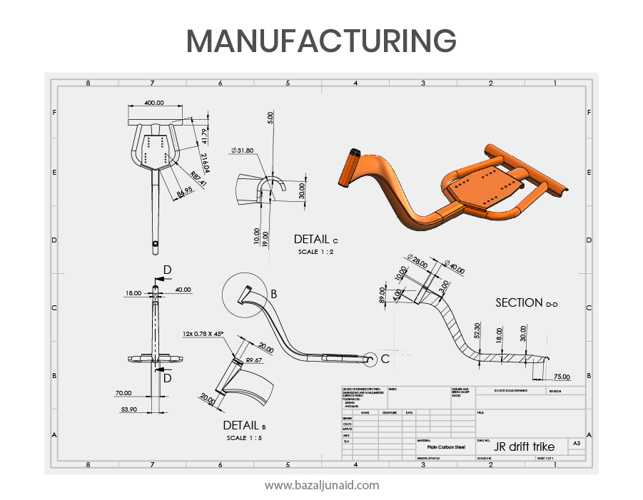
For the main frame, we will begin by building the shapes based on the sketch:
Step 1: We’ll use the Loft command, selecting two shapes and a guide line to generate a curved profile. This will create a surface, which we will then thicken to 3mm.
Step 2: Next, we will apply the Sweep command with a circular profile to create the supports on both sides of the frame. We’ll also use a shape extrusion to form the rear axle support.
Step 3: To attach the saddle to the frame, we will add a plate. This plate will be created using sheet metal features to ensure a proper fit.
Step 4: Finally, we will ensure that the entire model is hollow with a consistent 3mm wall thickness. This thickness can be adjusted later after simulating the Factor of Safety and analyzing structural performance.
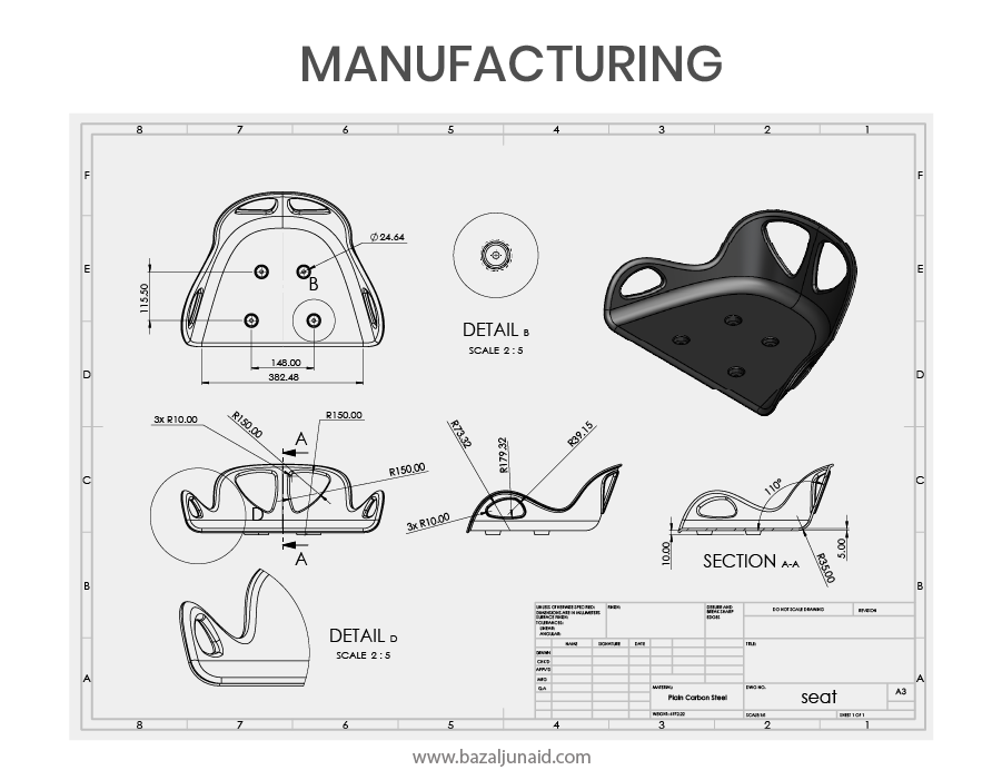
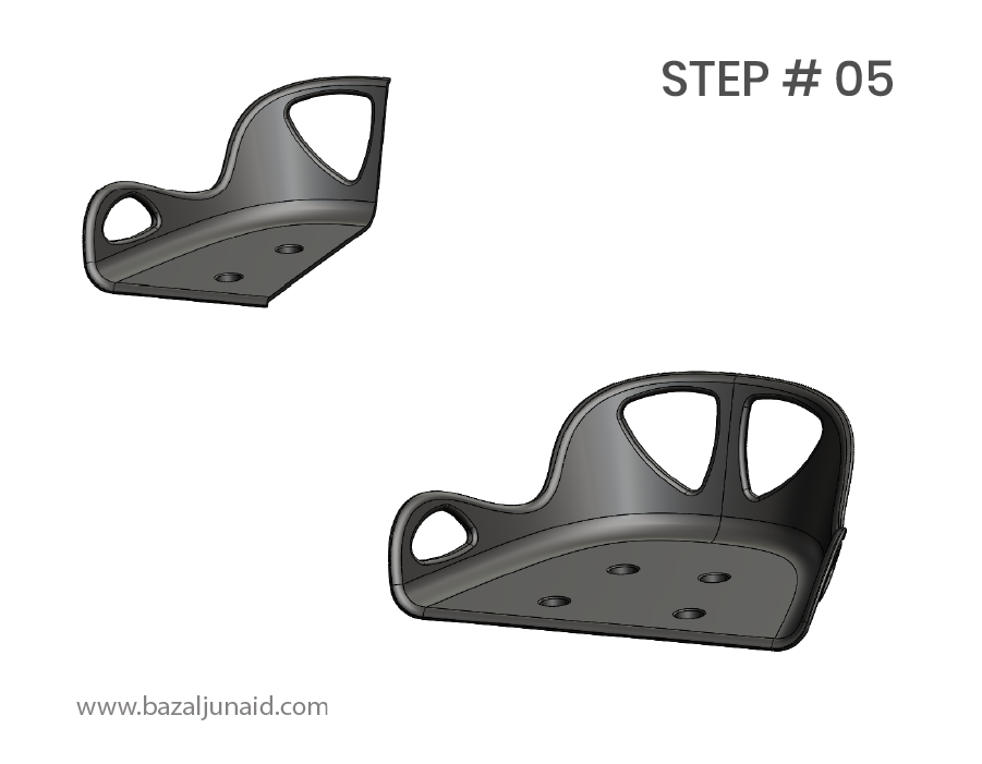
The saddle will be manufactured using injection molding, so it’s crucial to incorporate a draft angle for ease of production.
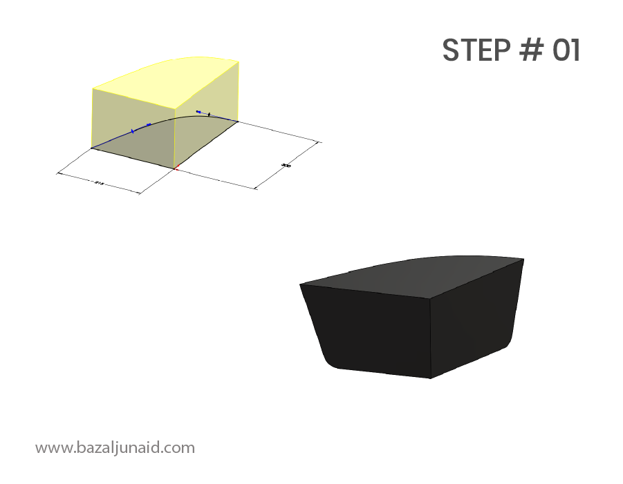
Step 1: We begin with a solid block representing half of the seat, and add a slight draft angle to the block to facilitate the molding process.
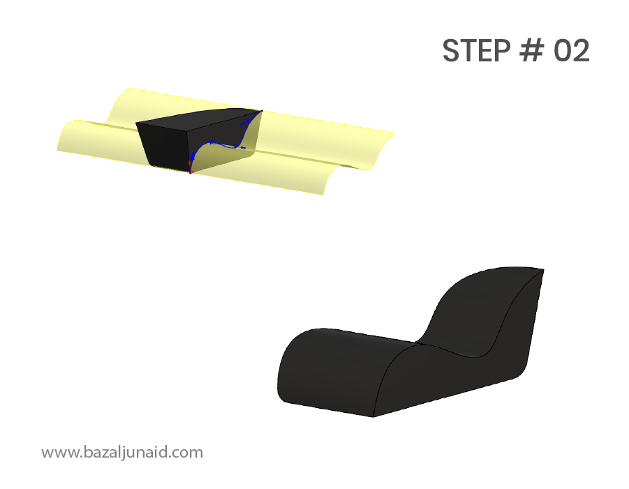
Step 2: The block is then split along the right plane to achieve the desired profile for the saddle.
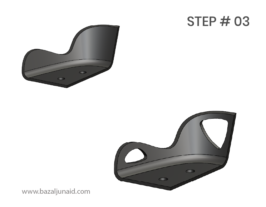
Step 3: Next, we apply a shell feature to hollow out the seat. Two extruded cuts are made from the front and right plane to create the necessary holes.
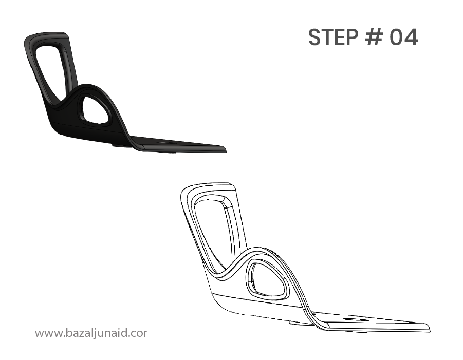
Step 4: To form a small extruded lip around the edges, we apply another shell feature on the opposite side of the seat.
Step 5: Finally, we mirror the entire model to complete the saddle design.
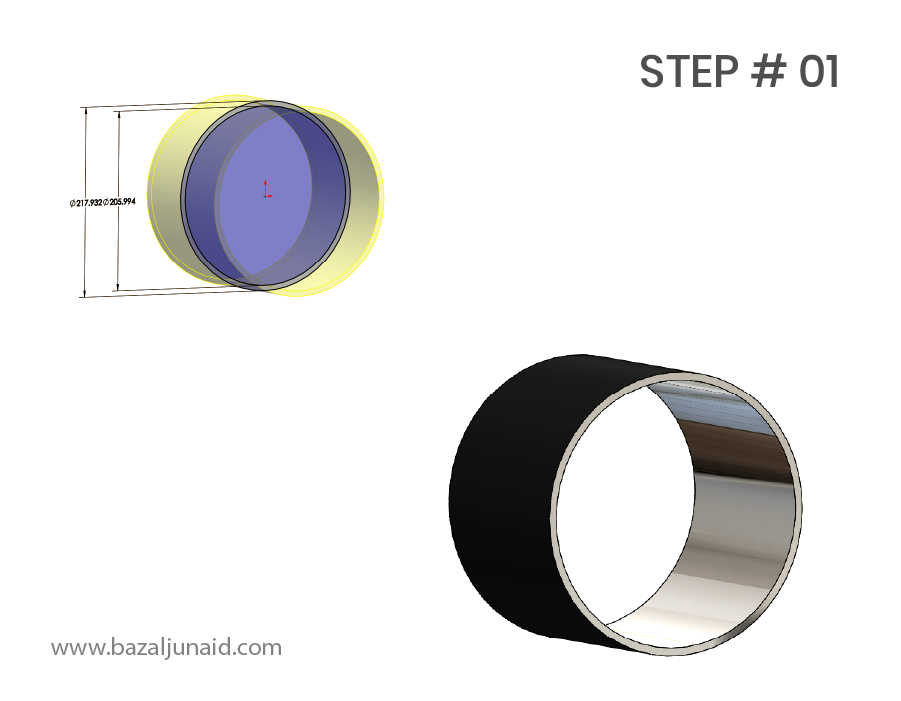
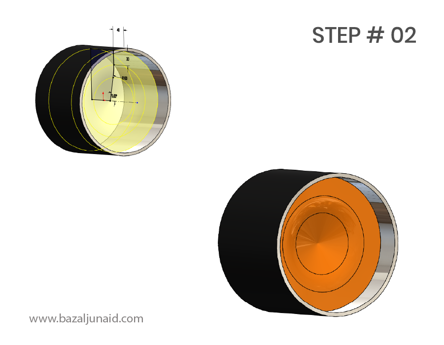
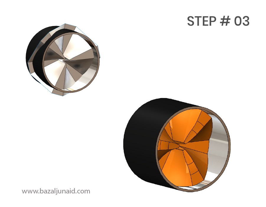
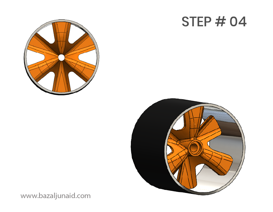
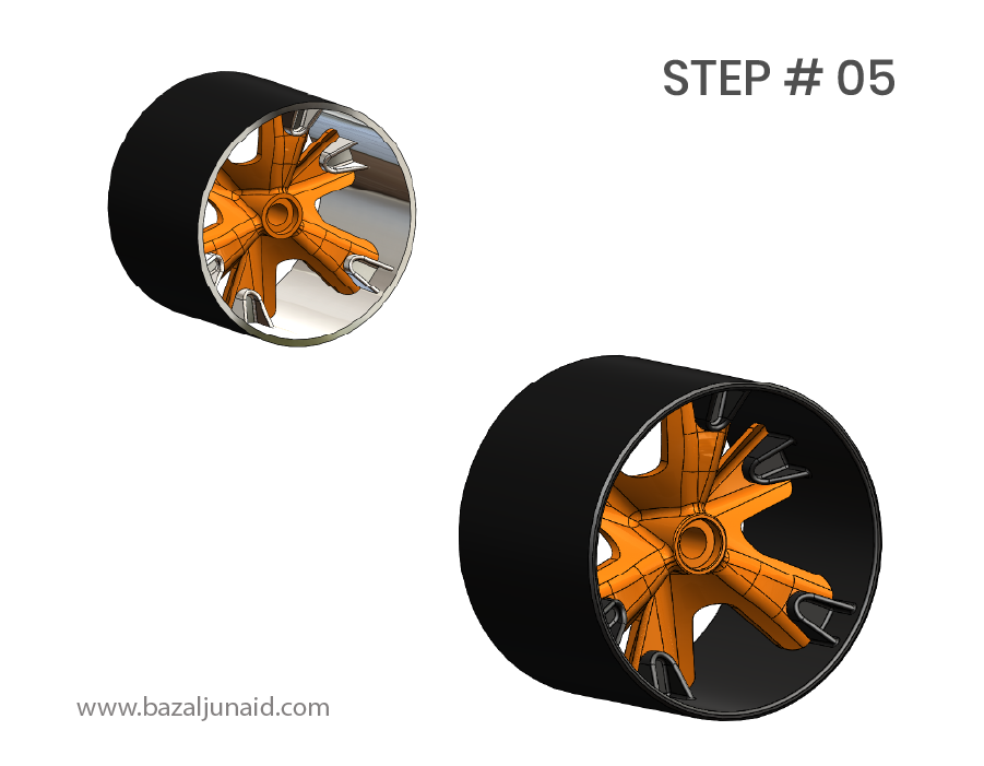
The wheels are made of nylon to reduce grip on the road and facilitate easier drifting. We need to create a support structure that will attach the wheel to the axle while also distributing the weight evenly across the wheel’s surface.
Step 1: I started by extruding a circular profile to create the outer cylinder, which forms the basic shape of the wheel.
Step 2: Then, I used surface modeling to revolve a sketch around the appropriate axis, refining the shape of the wheel.
Step 3: I created two surfaces on different reference planes along the Z-axis, then patterned these surfaces to create a consistent structure. These were used to slit the main surface and define the wheel’s geometry.
Step 4: To smooth the edges and add a more polished appearance, I applied fillets to the necessary areas.
Step 5: Finally, I added the support structures to connect the main body of the wheel to the rim, ensuring the wheel can be securely attached to the axle and distribute the load effectively.
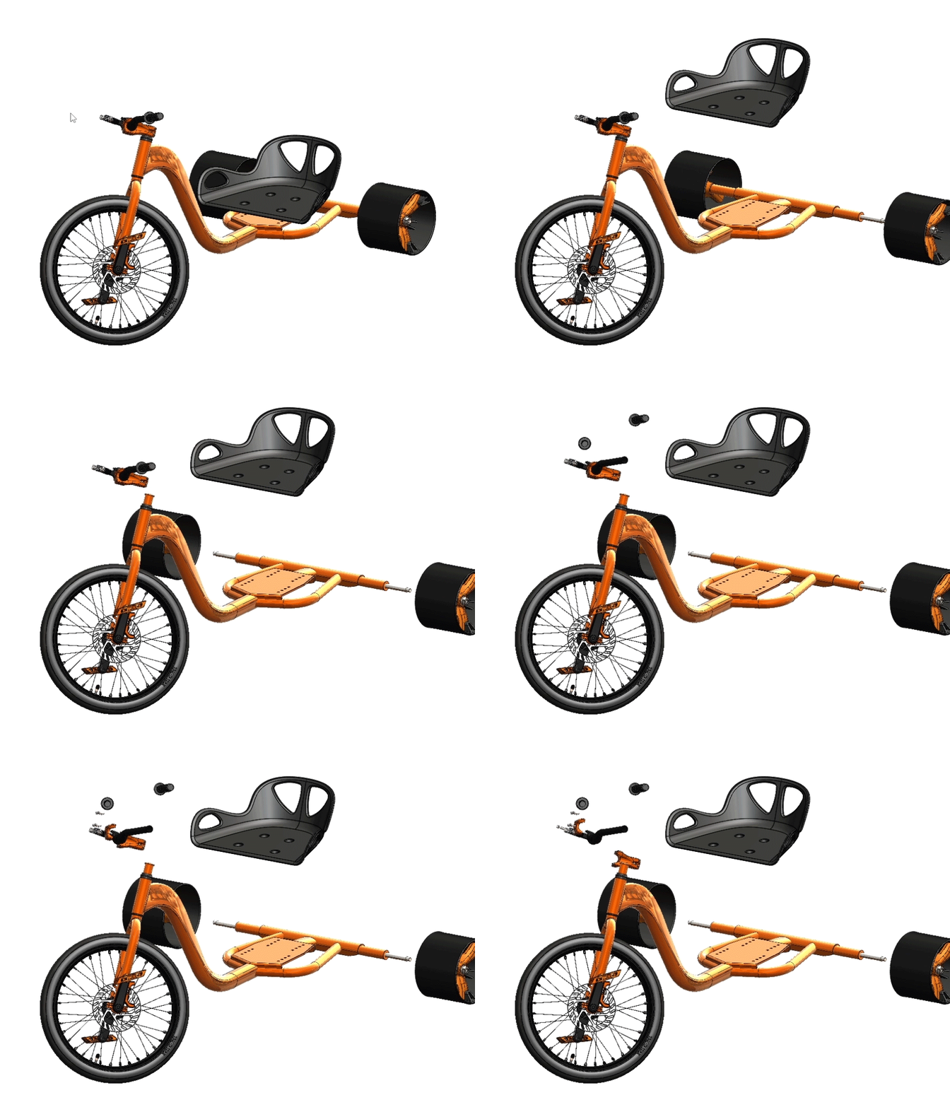
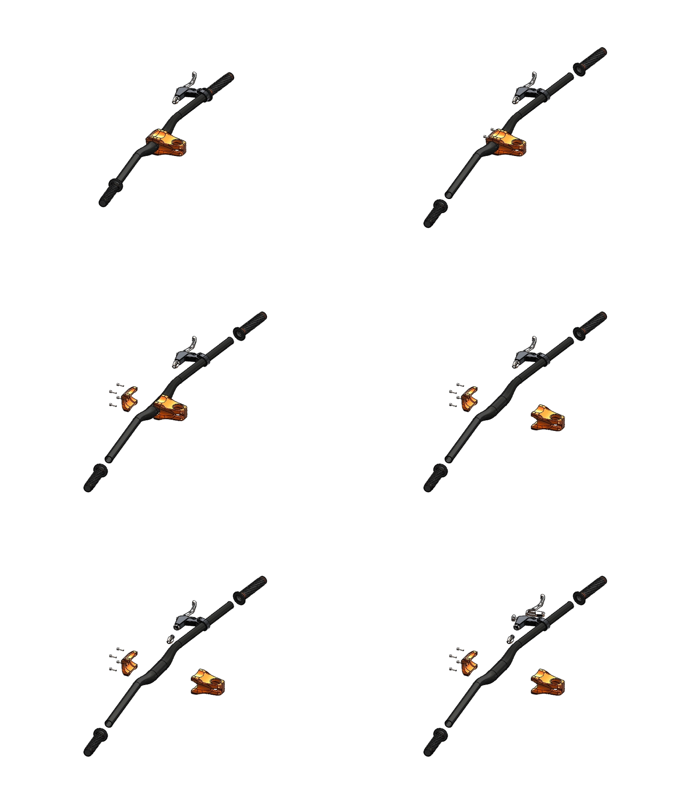
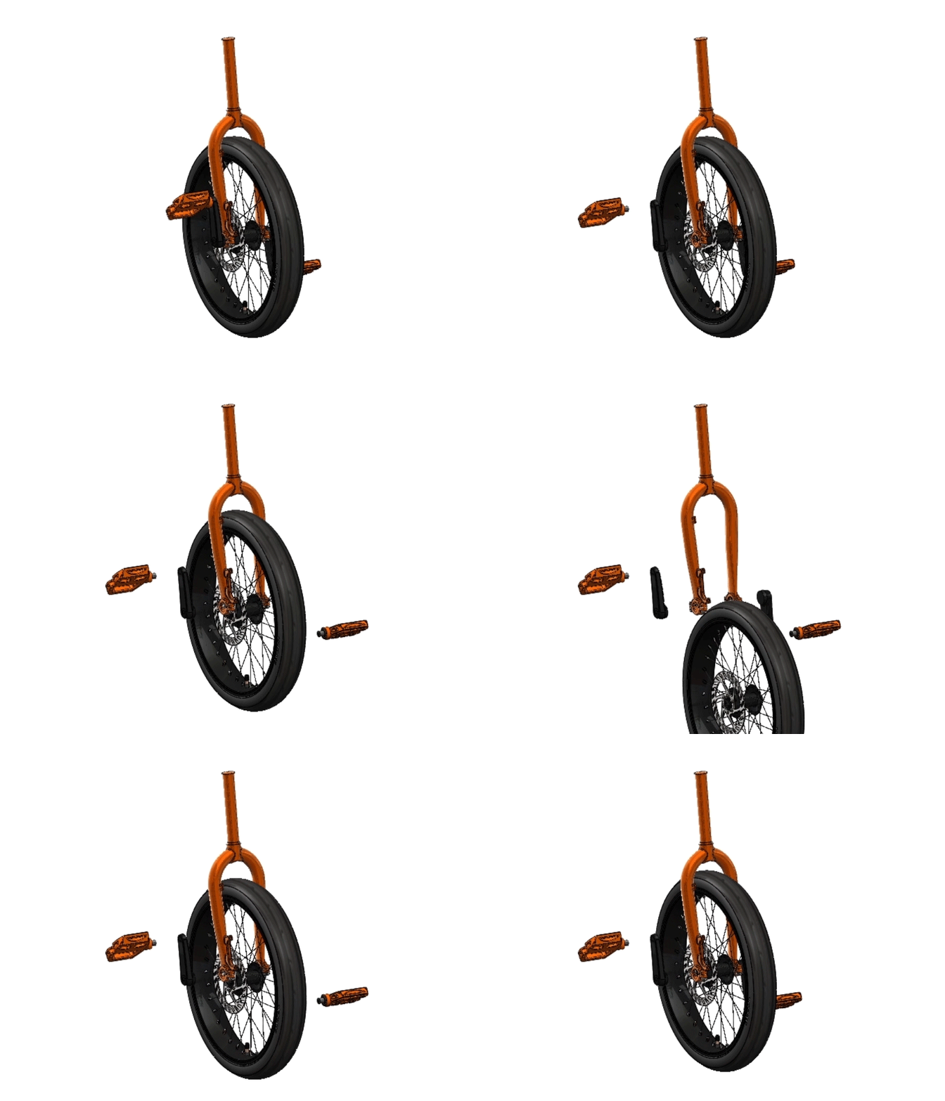
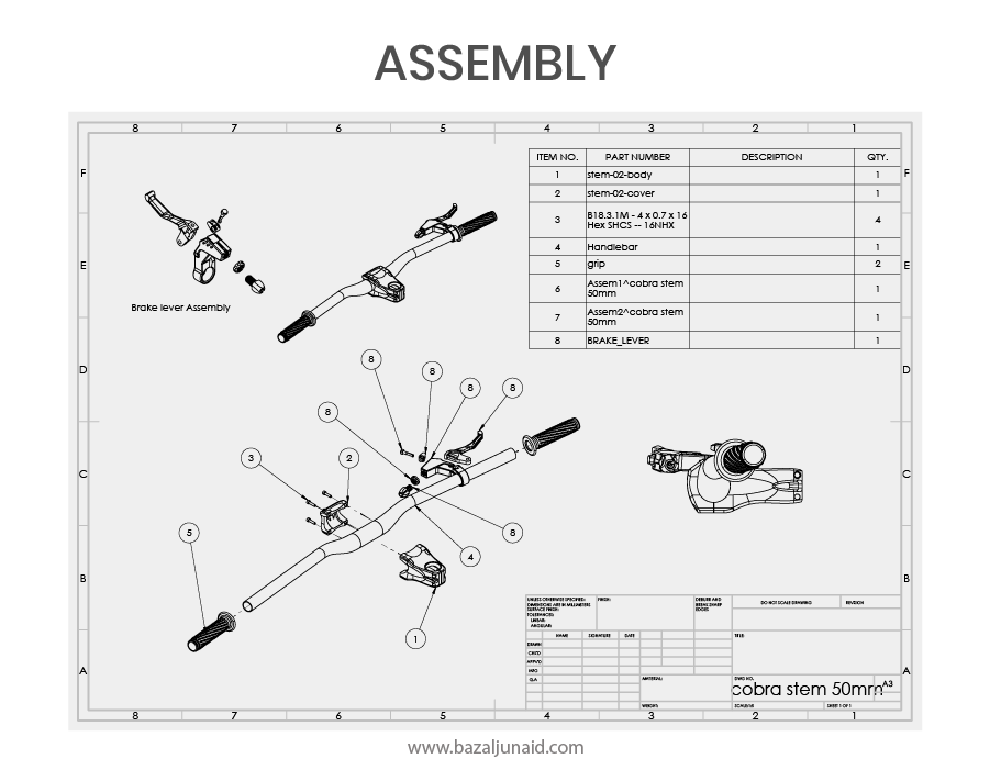
The assembly of this product is relatively straightforward, utilizing basic mates for positioning and alignment. However, to simplify the process and improve organization, I created subassemblies for the key components.
Finite Element Analysis (FEA) of the frame will help us understand its behavior under load and assess its deformation. This analysis will determine if the frame can safely support a 200 kg load. The material chosen for this model is stainless steel.
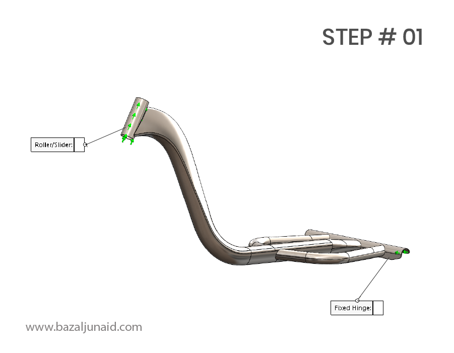
Step 1: I applied fixtures at both ends of the frame. A roller slider was placed on the top, allowing movement along the X-axis, while a fixed hinge was applied to the rear support, allowing rotation only.
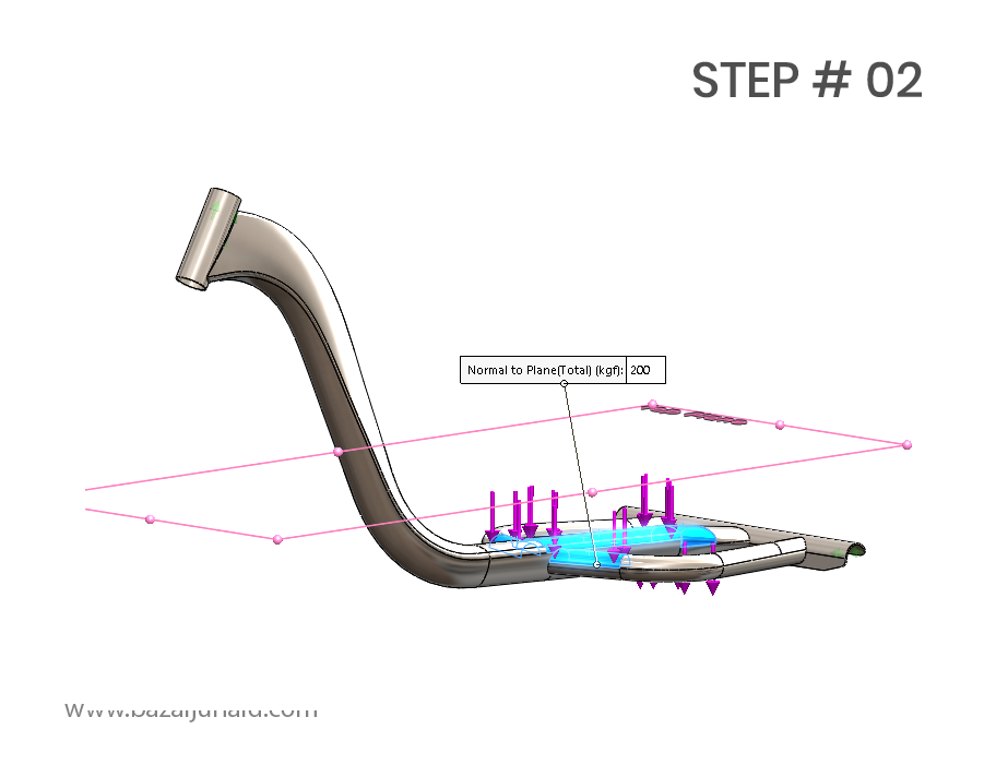
Step 2: I applied a 200 kgf load to the frame faces where the saddle will be attached, simulating the weight it will carry during use.
Step 3: I performed an automatic mesh with standard quality settings. Later, we can refine the mesh in areas of high stress to obtain more detailed results and ensure accurate analysis of the frame’s performance.

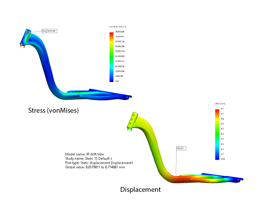
These results help us strike a balance between the material choice, design, and safety of the product.
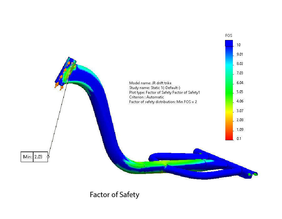
We observed that the maximum stress occurs at the joint on the top side of the frame, which also shows the minimum Factor of Safety (FOS) at that point.
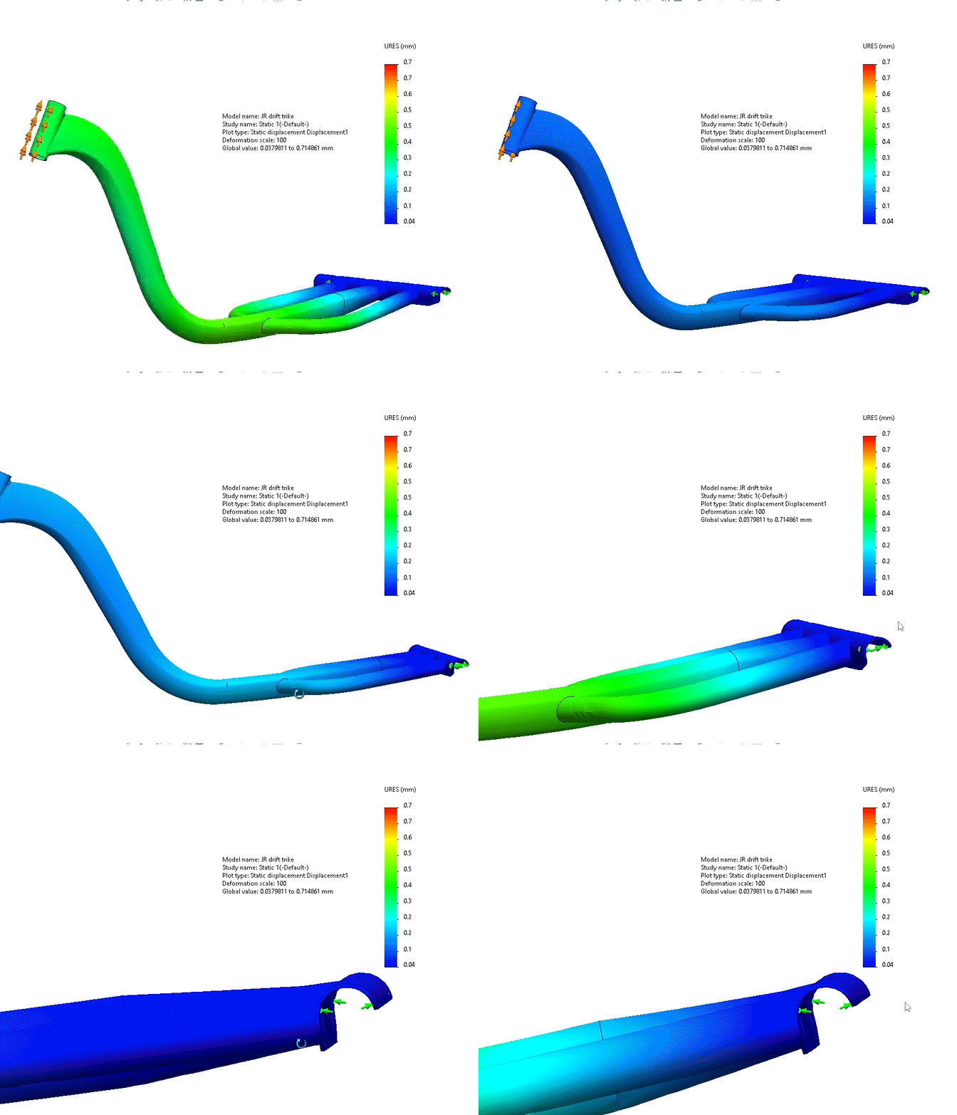
The minimum FOS is 2, which is considered acceptable for this type of product. The maximum deformation is 0.7 mm, which is quite small and within tolerance.
Based on the analysis, adjustments can be made to the design, such as changing the material, altering the thickness, or adding additional supports to increase strength. Conversely, modifications can also be made to reduce the cost by optimizing these factors.
Additionally, we can conduct a dynamic study to simulate real-world scenarios, such as a bump on the road, to further assess the frame’s durability and ensure it can withstand such conditions.
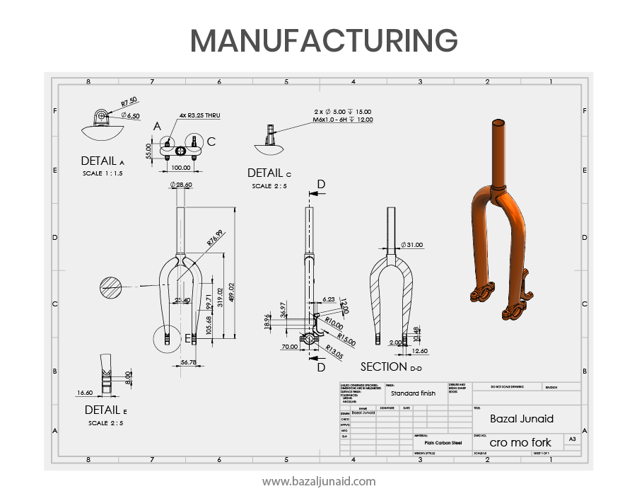
These technical drawings have been created to facilitate the manufacturing and assembly of the product. For more precision and higher performance parts, Geometric Dimensioning and Tolerancing (GD&T) methods have been applied to ensure accurate specifications and fit.
